
ATV Frequency Transponder
|
|
|
In order to receive ATV signals on a regular television you must use a frequency converter. The converter published here was taken from an original project from EA1KO published on november 1985 of the spannish issue of CQ magazine. This converter shifts the 430-440 MHz signals down to 174-176 MHz somewere about chanel 5 VHF.
Theory of operation
As you can see from the schematics shown here you can see that the signal is feed through a 22pF ceramic capacitor and a PCB strap tuned together with a variable capacitor; the soldering must be positioned at a point where the circuits impedance is adequate. This strap is associated with the base of the BFR90 transistor ( low noise and high gain transistor ) that will handle the amplification of incoming signals, on the transistor´s collector the signal is extracted through a 15 pF at a precise point of a PCB strap that is also tuned together with a varible capacitor.
This signal feeds the base of the next stage that performs as mixer stage, that has on its output a wide band tuned output RF transformer on this case tuned around the chanel 5 ( 174-178 MHz ). The local oscilator is based upon a BF245 FET transistor that provides good stability operating on a direct oscilation without any physical conection with the mixing stage, therefore avoiding any pulling or interaction with the rest of the circuit. The mixing is done by inducing the mixing stage through the oscilators coil. The resistors are biasing networks and the 1nF capacitors are decoupling capacitors, for reference you should know that the oscilator frequency turns around 260 MHz and the author states that the idea was taken form J. Wood, G3YQC, on his publication TV FOR AMATEURS.
|
Construction |
|
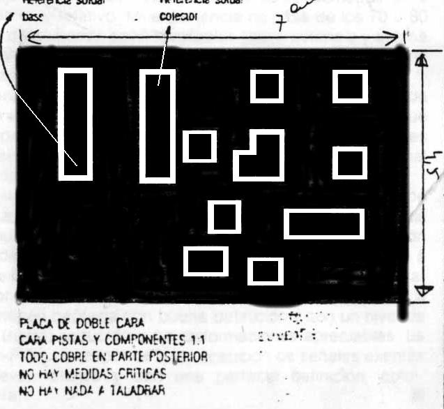
The board is constructed with duble sided epoxy PCB keeping all the coper of the oposite face for shielding purposes. The straps and pads are made directly on the components side.
To make this PCB ,first i placed i´ve cuted the board to it´s size ( 7cm x 4,5 cm )and then placed the drawing over the PCB, then with a small driller, marked the corners of all the straps and pads for guidance purposes. After that and with the help of a ruller "scratched" gaps on the PCB to draw out the pads and straps. The "scratcher" that i used is a regular thin pointed edged tool to scratch the coper out of the board.
L1, L2 - Tuned straps builded directly on the PCB.
L3 - 2 turns of 1 mm wire and 5 mm Æ .
L4 - 5 turns 0.20 mm ( collector side) + 2 turns 0.20 mm ( output winding ) all spaced about 0.5mm over a IF VHF coil; this is not critical.
CH - 15 turns 0.15 mm winded over a 1MW 1/4 W resistor soldering the tips on the resistor terminals.
TESTING AND TUNING
You must first tune your TV set around channel 5 and set your UHF transceiver to a frequency of 431.250 MHz, set your radio to transmit and start tuning your TV set until you get a black screen, this means that you are just about the transponded frequency, now connect your transponder to your external antenna and ask someone near you to start an ATV broadcast, ajust CV1 with a plastic screwdriver for maximum signal strenght, do the same with CV2 and go back again to CV1, repeat this as many times needed until you get the best picture quality, final adjustment is the interior of L4, adjust also for maximum signal.
|
|
