
A Wheatstone bridge regenerative (WBR) receiver with 2N7002
Basic principles
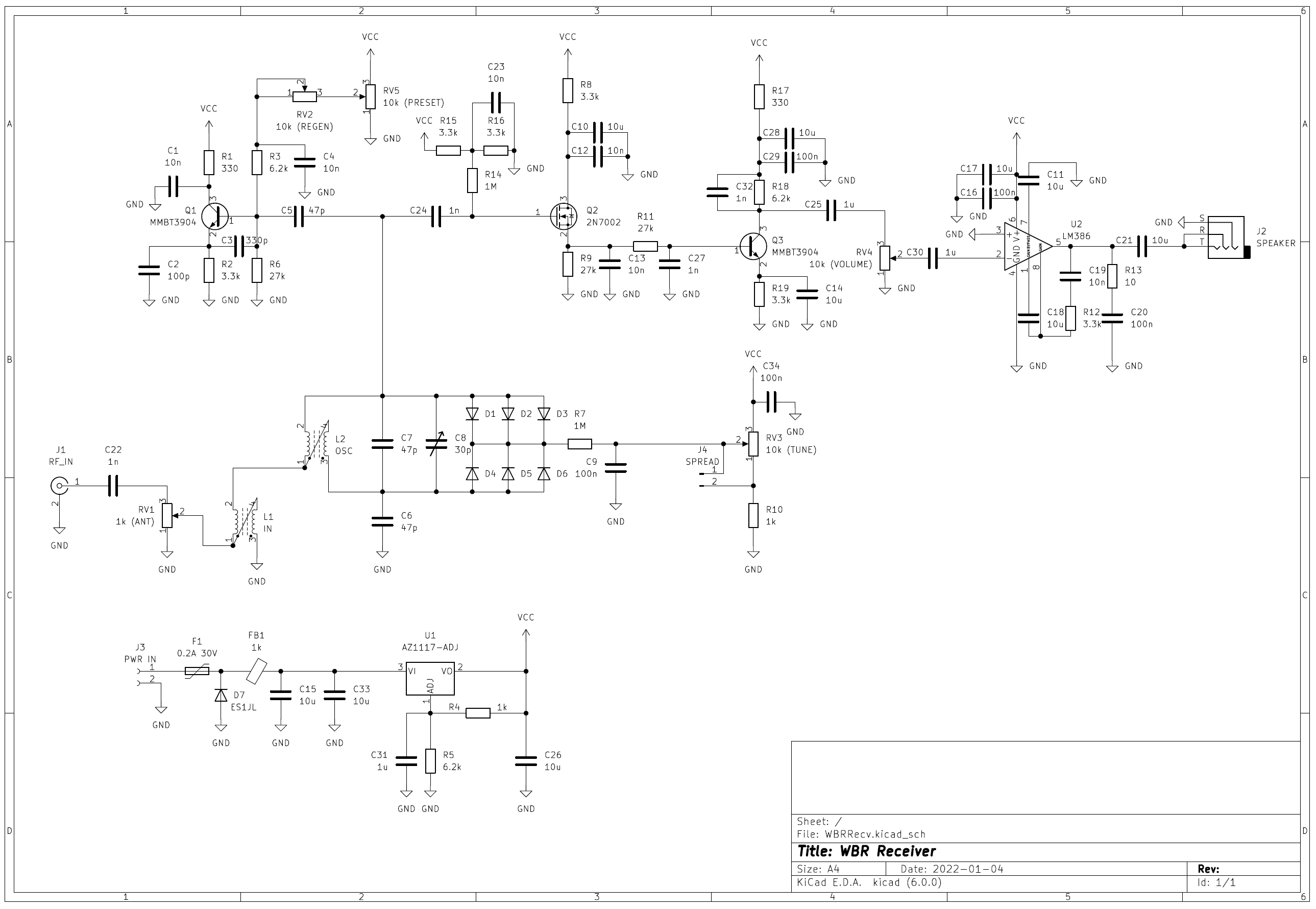
The circuit is based on the N1BYT’s WBR receiver, as shown in the schematic below. Q1 is the core of a Colpitts oscillator circuit, and RV2 and RV5 adjust whether the circuit oscillates (i.e., regeneration strength). L2, C7, C8, and six diodes D1 to D6 form the oscillation tank circuit. The input signal is attenuated by RV1, and then fed into the middle tap of L2 with L1. The DC path of the variable capacitance diode anode is provided by L1.
The tuning voltage is generated by a voltage divider composed of RV3 and R10. When J4 is open, the voltage divided by RV3 is linearly related to the position \(a\) of wiper 2 (with a value range of \(0\cdots1\), where the wiper is at the 1 end when \(a=0\), and at the 3 end when \(a=1\)). Since the capacitance of the variable capacitance diode decreases as the voltage increases, and the change is smaller at high voltages, the frequency changes more quickly when the wiper of RV3 is near the low end (the first few turns of the multi-turn potentiometer); while the frequency changes more slowly when the wiper is near the high end (the later turns of the multi-turn potentiometer).
When J4 is shorted, the relationship between the output voltage and the position \(a\) of wiper 2 is \(V_\mathrm{out}=V_\mathrm{cc}\cdot\frac{1}{1+10(1-a)}\). Obviously, when \(a=0\) or \(a=1\), the output voltage is the same as when J4 is open, while in the middle position, the change exhibits a slow-to-fast trend. This trend is more pronounced than the trend of the capacitance of the variable capacitance diode changing with voltage, so when the multi-turn potentiometer is at the first few turns, the frequency changes more slowly, while at the later turns, the frequency changes more quickly.
The original WBR receiver used a junction field-effect transistor (JFET) MPF102 for detection, but here it is replaced with a MOSFET 2N7002. Since 2N7002 is an enhancement-type device, a voltage divider circuit composed of R15, R16, and C23 is used to supply gate bias voltage. The value of R14 is large enough, so the bias circuit has minimal impact on the oscillator. Q2 works in a state with very small drain current, playing the role of detection. Q3, U2, and related parts form the audio amplifier. U1 and its external parts form the voltage regulator circuit (VCC voltage is 9V).
The equivalent load capacitance of the oscillator and detector, C6, as well as the two parts of L2, form a Wheatstone bridge as shown below. In the figure, L11 and L12 represent the two parts of L1, L21 and L22 represent the two parts of L2, Cl represents the equivalent load capacitance of the oscillator and detector, Ct represents the capacitance of the resonant tank circuit, V1 represents the equivalent input voltage, and V2 represents the equivalent oscillation voltage.
 The voltage at the OSC and INPUT terminals in the circuit is shown below:
 There is almost no oscillation voltage at the INPUT point in the circuit (the residual amount depends on the balance of the bridge), but signals fed in from this point can still reach the OSC point in the circuit (i.e. the base of Q1). The benefits of feeding the signal in from this point are:
- The change in antenna load has almost no effect on the oscillation frequency;
- When Q1 is in the oscillation state, the leakage from the oscillator to the antenna is minimal (generally easily controlled to within -70dBm).
The DC potential at the balanced state of the bridge is provided by the grounded point at the bottom of L1. RV1 attenuates the input signal.
For the external signal on the base, Q1 operates in an amplification state with positive feedback, which is the same as a typical regenerative receiver. Under the effect of positive feedback, the sensitivity and selectivity of the receiver will be greatly improved. When operating near the critical point of oscillation, the sensitivity and selectivity of the receiver are at their best. If Q1 operates in the state of just starting oscillation, it can also serve as a beat frequency oscillator (BFO) for receiving CW and SSB signals.
Project
Designed with KiCad 6.0. A four-layer board with dimensions of 100mm×50mm is used. The assembled PCB is shown in the following picture.

Project files can be downloaded here. git repository is at https://github.com/BH1PHL/WBRRecv_2N7002.
Components
- Fixed resistors are 0805 1% surface mount type.
- F1 is an 0805 0.2A self-recovery fuse (voltage rating of 24V or higher). FB1 is an 0805 ferrite bead (1kΩ@100MHz). The values of these two components are not critical.
- Diodes D1 to D7 are ES1JL fast recovery diodes (Shandong Jingdao Microelectronics) , but other types and brands can be tried. Note that rectifier diodes are used instead of variable capacitance diodes for D1 to D6, and the reverse capacitance characteristics of rectifier diodes of different types and brands may not be the same, and the number of parallel connections needs to be determined through experimentation.
- Transistors Q1 and Q3 are MMBT3904 (SOT-23 package).
- Transistor Q2 is WST2N7002 (WINSOK), other manufacturers’ 2N7002 products can also be tried.
- Fixed capacitors are all multi-layer ceramic capacitors (MLCC), 10uF capacitors use 1206 package, and the remaining capacitors use 0805 package. NP0(C0G) capacitors are used for less than or equal to 1nF, and X7R/X5R capacitors for greater than 1nF. When selecting capacitors, pay attention to the voltage rating (using a voltage rating of 25V or higher is safe).
- C8 is a common 6mm plastic-sealed trimmer capacitor (9-30p, green). Note that poor-quality capacitors of this type may encounter internal open circuit situations. It is recommended to measure it before soldering, or use a similar-sized ceramic shell trimmer capacitor.
- RV1, RV2, RV4 are 1-gang potentiometers with the same package as ALPS RK097; RV3 is a multi-turn potentiometer (such as BOURNS 3590S-2), which is led out by a 2.54mm pin header. RV5 is a PCB mount trimmer potentiometer with the same package as BOURNS 3362P.
- U1 is a SOT-223 package adjustable 1117 linear regulator supporting ceramic capacitors, such as AZ1117, SPX1117, AP1117, etc. Note that if the original LM1117 or the most common AMS1117 is used, C26 may need to be a tantalum capacitor.
- U2 is LM386 or any compatible product.
- J1 is a edge mount SMA jack, J2 is a 5-pin 3.5mm headphone socket, J3 is a 3.5mm pitch terminal block (plug and socket, and J4 is a 2.54mm pin header with a shunt cap.
- L1 is two turns of bifilar winding on a ferrite ring with \(\mu_\mathrm{i}=300\) and OD×ID×h=12.7mm×7.9mm×6.4mm, .
- L2 uses a T50-6 iron powder core. The number of turns (bifilar winding), C7, and J4 for different bands are shown in the table below:
| Band | L2 (T50-6) | C7 | J4 | frequency range (approx.) |
|---|---|---|---|---|
| 40m | 17T×2 | 47p | short | 6990~7220kHz |
| 30m | 15T×2 | 0p | open | 9.6~10.2MHz |
| 20m | 11T×2 | 0p | open | 13.5~14.4MHz |
Adjustment
Required equipment: power supply, signal generator, headphones or speaker
Optional equipment: attenuator, oscilloscope
Steps:
- Adjust the REGEN potentiometer to 75%; adjust the VOLUME potentiometer to the middle; adjust the TUNE multi-turn potentiometer to the minimum.
- Connect the power supply, headphones or speakers, and signal generator, and set the power supply to 12V.
- Input a signal of about 0.1mV: set the signal generator to 100mVpp + 60dB attenuator, adjust the ANT potentiometer to the maximum; or 1mVpp + adjust the ANT potentiometer to about 1/10.
- Turn on the power supply and signal generator. Adjust the VOLUME potentiometer to a comfortable volume.
- Adjust regeneration: adjust the PRESET trimmer potentiometer to make the oscillation just start (the background noise in the headphones suddenly becomes louder). Note: when the oscillation is too strong, the sound in the headphones may also be very low.
- Adjust the low-end coverage: set the signal generator to SWEEP mode, with a start frequency of 6.5MHz, an end frequency of 7.5MHz, and a time of 0.2s. Adjust the adjustable capacitor C8 to make sound appear in the headphones. Adjust the signal generator sweep upper and lower limits and adjustable capacitor C8 to narrow the frequency range, so that the TUNE multi-turn potentiometer receives a frequency of around 6990kHz at the minimum (lowest receiving frequency).
- Confirm high-end coverage and regeneration control: set the signal generator to 7.2MHz, adjust the TUNE multi-turn potentiometer until the signal is received, and adjust the REGEN potentiometer to confirm that the regeneration control is still working (there is a point where the background noise suddenly becomes louder and a whistling sound appears when adjusting from low to high).
- If necessary, use hot-melt glue or wax to seal the coil (after sealing, it may be necessary to fine-tune the adjustable capacitor C8).
Notes:
- When adjusting the low-end coverage (step 6), 2-3 turns of wire can be wounded on the T50-6 core and connected to an oscilloscope or a high-impedance input frequency counter, so the oscillation frequency (same as the receiving frequency) can be observed and adjusted.
- When adjusting (especially fine-tuning), the signal input end can also be connected to a receiver with spectrum display (such as the G90S transceiver) to observe the frequency of the signal leaked from the oscillator to the antenna.
Usage
-
Connect the antenna, power supply, headphones or speaker. The power supply voltage should be above 10.5V, and the high voltage limit is determined by the maximum ratings of the components used, such as the 1117 voltage regulator, input fuse, filtering capacitor, etc. Pay attention to the polarity of the power supply!
-
Adjust the ANT and VOLUME potentiometers to the middle position. Adjust the REGEN potentiometer to the point just before oscillation (when the background noise suddenly increases). Adjust the VOLUME potentiometer to a comfortable volume. Note: it is normal to have broadcast interference when there is no oscillation. If there is still broadcast interference after oscillation, adjust the ANT potentiometer to the left to increase the input attenuation; if there is no broadcast interference whether there is oscillation or not, it indicates that there is no strong interference broadcast radio station nearby, and the ANT potentiometer can be adjusted to the right to reduce the input attenuation.
-
Adjust the TUNE potentiometer to change receving frequency. Generally, the REGEN potentiometer needs to be adjusted at the same time to make the regeneration work near the oscillation point for the best effect. Note that as the tuning frequency increases, the regeneration will become stronger. If you want to keep the regeneration strength unchanged, you should adjust the REGEN potentiometer to the left appropriately, and vice versa.
-
When receiving CW/SSB stations, the regeneration should be adjusted to the point just after oscillation (with the REGEN potentiometer slightly to the right of the oscillation point) for the best effect. When receiving AM stations, the regeneration should be adjusted to the point just before oscillation (with the REGEN potentiometer slightly to the left of the oscillation point) for the best effect.