Some experiments on My4TH (4): Peripherals
EEPROM Card and Backplane
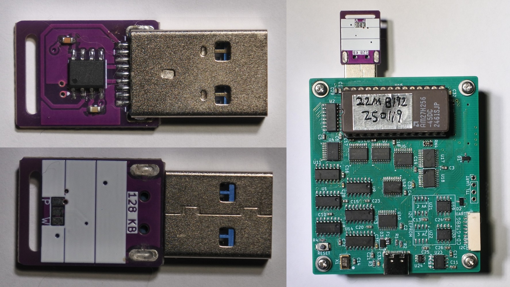
EEPROM Card
For EEPROM cards, firmware provided on this website arranges adjacent blocks on the same EEPROM chip, with block numbers ordered according to EEPROM addresses.
The EEPROM card card uses a USB 3.0 Type-A interface, where the power contacts are compatible with standard USB interfaces, and the signal contacts are used for I2C interface and addressing:
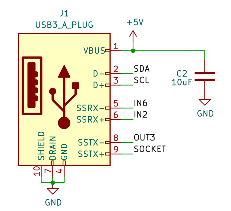
SOCKET connects to EEPROM address line A1:

The KiCad project files of the EEPROM card can be downloaded here.
Backplane
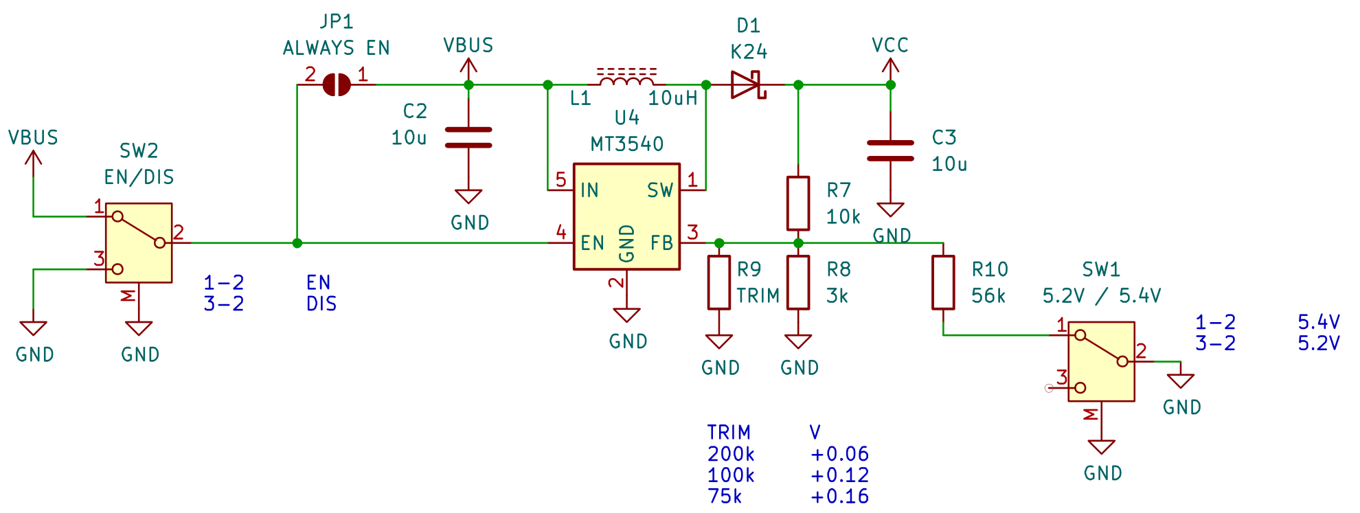
The KiCad project files for the backplane used to connect storage expansion cards and provide 5.2V/5.4V power (for 20MHz and 22.1184MHz) can be downloaded here. The backplane also includes a DS1307 real-time clock and PCA9557 I/O expansion.

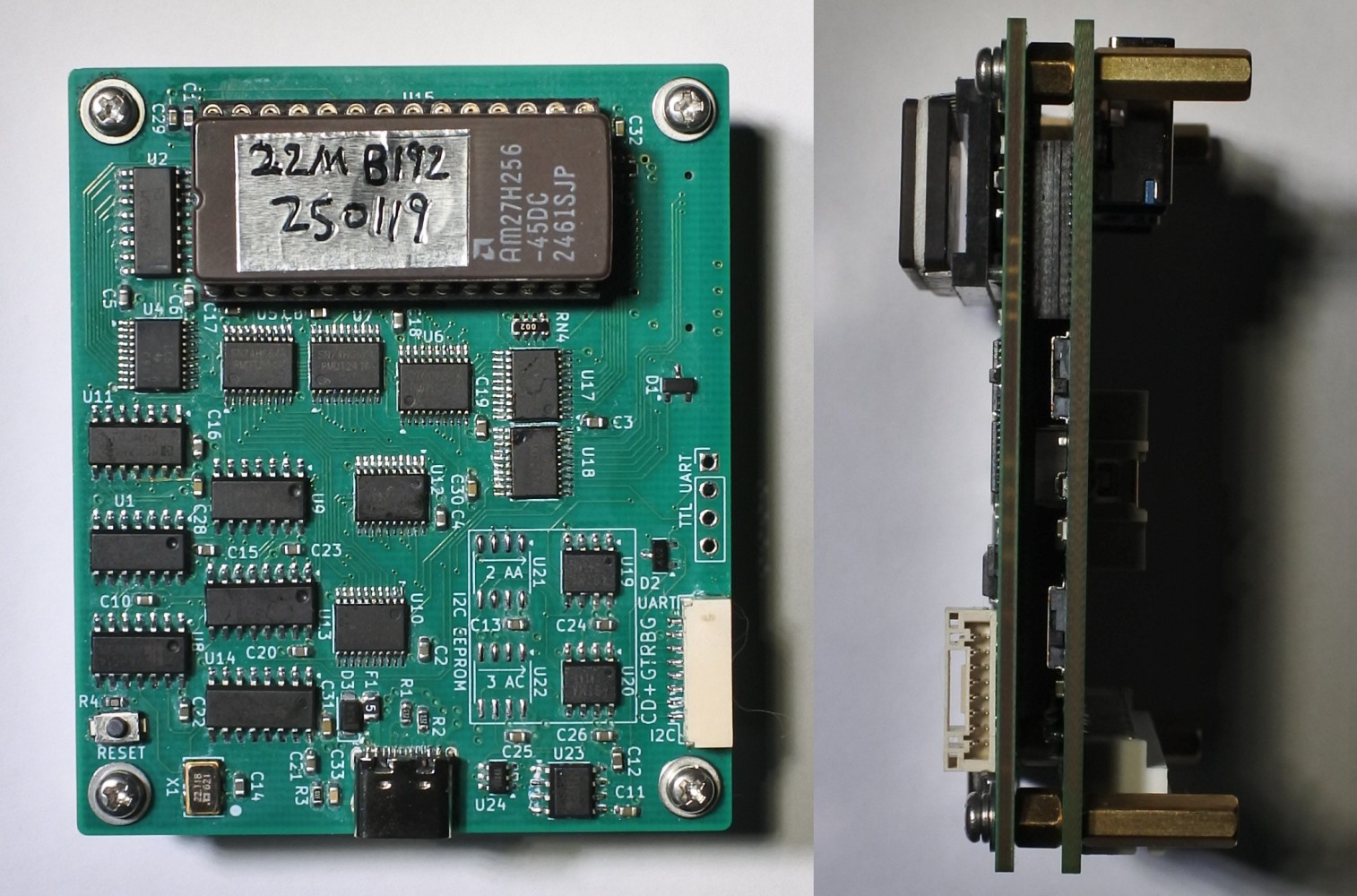
The connectors between My4TH SMT and the backplane are generic 0.8mm pitch doble slots board-to-board 2x16 connectors (total height 4mm, such as this one and this one, or this one. Socket on My4TH board, plug on backplane.) The Bus connector is a PHB 2x20 2mm pitch right angle socket.
The power supply circuit is shown in the figure below. SW1 and SW2 are 7-pin toggle switches with a size of 6.6x2.7mm and a pin pitch of 1.5mm (for example, this one).
Drivers for DS1307 and PCA9557
The DS1307 real-time clock on the board occupies the I2C address $D0.
\ C DS1307 Driver
: dec2bcd ( dec -- bcd ) 10 /mod 16 * + ; \ 2 digits only
: bcd2dec ( bcd -- dec ) 16 /mod 10 * + ;
: rtc-rh  $d0 i2c-rr drop ;   : rtc-wh  $d0 i2c-wr drop ;
\ 0:sec(use rtc-sc@/!) 1:min 2:hour 3:day 4:date 5:month 6:year
: rtc-r ( reg -- dat ) rtc-rh bcd2dec ;
: rtc-w ( dat reg -- ) swap dec2bcd swap rtc-wh ;
: rtc-sc@  0 rtc-rh 127 and bcd2dec ;
: rtc-sc!  dec2bcd 0 rtc-rh 128 and or 0 rtc-wh ;
: rtc-stop  0 rtc-rh 128 or 0 rtc-wh ;
: rtc-start  0 rtc-rh 127 and 0 rtc-wh ;
\ Forth 2012 Facility Extension word TIME&DATE
: time&date ( -- sec min hour date month year )
   rtc-sc@ 1 rtc-r 2 rtc-r 4 rtc-r 5 rtc-r 6 rtc-r 2000 + ;
When using the following driver, addr is the I2C address $34 of the PCA9557 I/O expander on the board.
\ C I2C PCA9557 Driver
: p57-pc ( addr -- ) $00 $02 rot i2c-wr drop ; \ polarity clear
: p57-dir ( dir addr -- ) swap $03 rot i2c-wr drop ;
: p57-wo ( val addr -- ) swap $01 rot i2c-wr drop ;
: p57-ro ( addr -- val ) $01 swap i2c-rr drop ;
: p57-ri ( addr -- val ) $00 swap i2c-rr drop ;
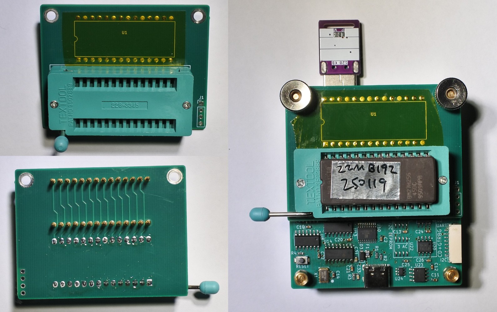
EPROM ZIF socket
ZIF socket allows for convenient testing of different EPROMs. The connection between the socket and the My4TH SMT board is made using 6mm pogo pins (such as this and this). The KiCad project files can be downloaded here.
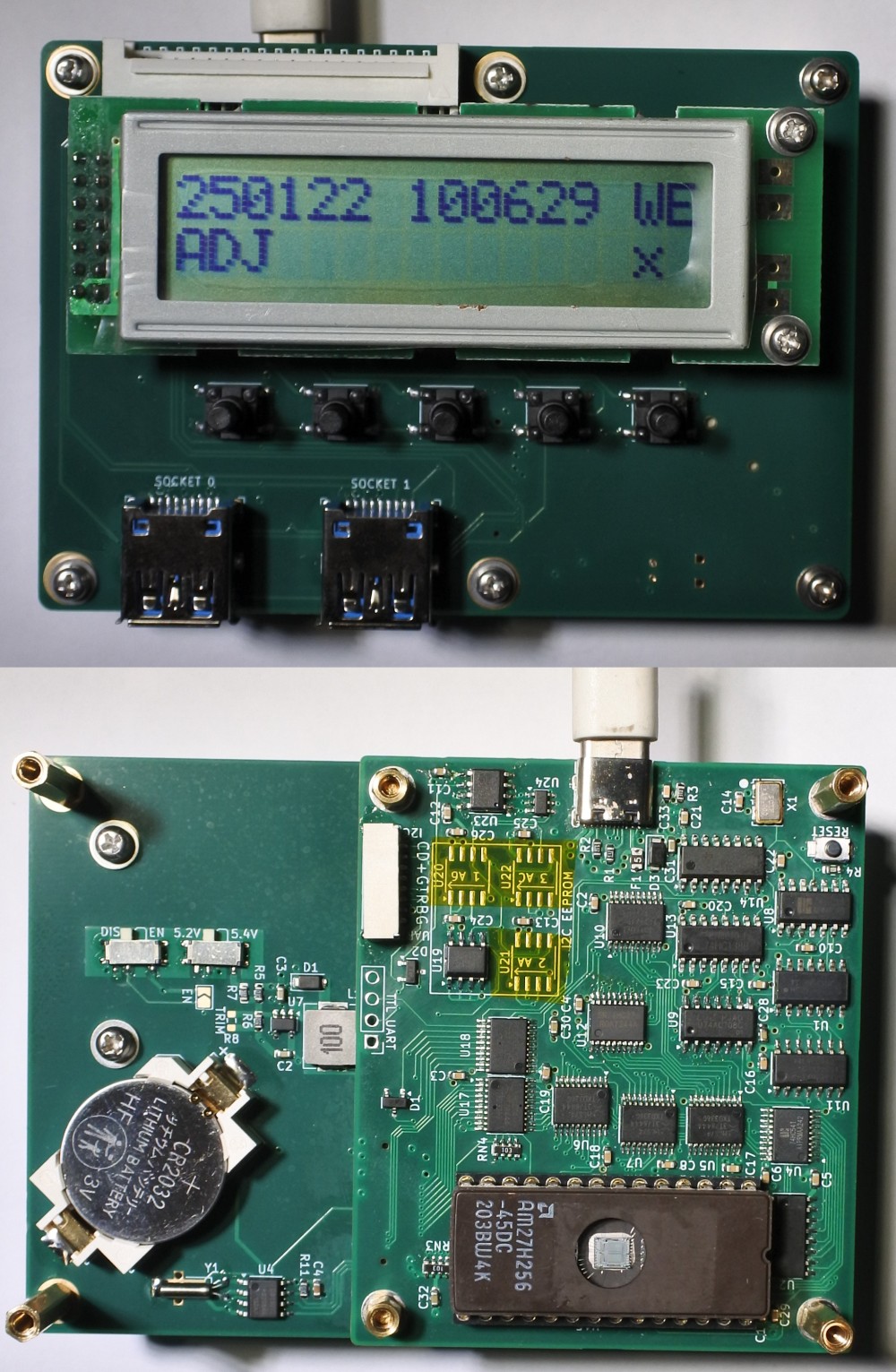
1602 LCD screen and buttons
With two PCA9557 I/O expanders and a 74HC165 shift register, the 1602 LCD screen and buttons can be driven using the I2C interface:

This is an example of a clock that uses a 1602 LCD screen, buttons, and a DS1307 real-time clock. The KiCad project files can be downloaded here.