
Some experiments on My4TH (1): Running at 16MHz
My4TH is a minimalist computer designed by Dennis Kuschel. This computer is extremely simplified in its design, employing a serial ALU and utilizing 16 74HC series CMOS logic devices along with microcodes from ROM for CPU. It runs the Forth system. Here are some experiments related to this computer.
Increasing the running speed
To ensure the state of the bus during reset, the original version of My4TH employs 10k resistors to pull down the data bus to GND. This introduces compatibility issues between TTL and HCMOS voltage levels: the outputs of RAM 62256 and ROM 27C256 conform to TTL levels, with a minimum high-level output voltage (\(V_\mathrm{OH}\)) of 2.4V; whereas the minimum high-level input voltage (\(V_\mathrm{IH}\)) for 74HC devices is \(0.7 V_\mathrm{cc}\), which is 3.5 V when powered at 5 V.
For My4TH, due to the low number of logic devices and the low fan-out of RAM and ROM on the data bus, the original version can still function properly at 10 MHz. However, pushing for higher speeds causes malfunction. The original author achieved 14 MHz by replacing certain 74HC parts with 74AC series. However, is there a simpler method to achieve a higher speed?
According to Fairchild’s application notes AN 319 and AN 368, the simplest method to make TTL-level outputs compatible with HCMOS-level inputs is to pull up the connection line between the TTL circuit’s output and the HCMOS circuit’s input. However, for My4TH, directly pulling up the data bus to \(V_\mathrm{cc}\) would affect the initial state of the data bus during reset, leading to abnormal initial values for the reset vector and control signals, making the system unable to operate when powered on. To ensure the correct initial state, it is necessary to pull down the data bus during reset and then pull it up in the first clock cycle after reset.
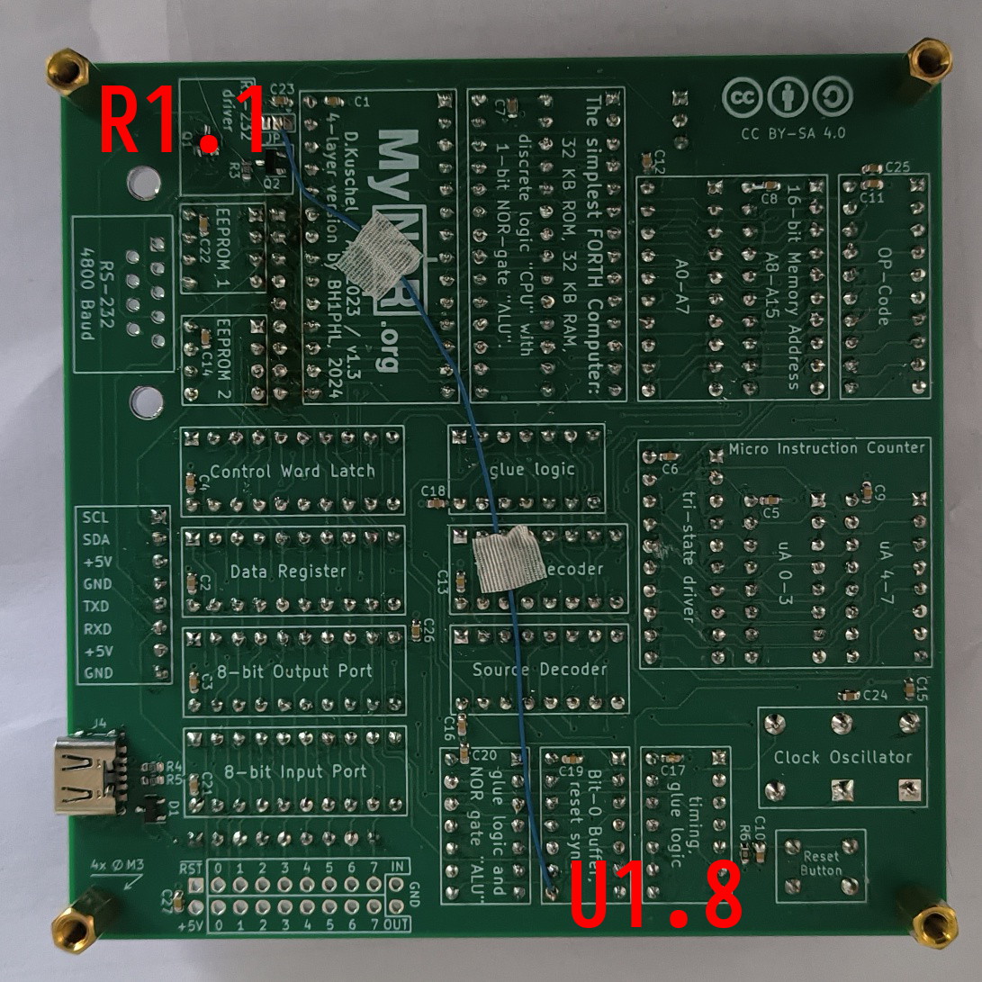
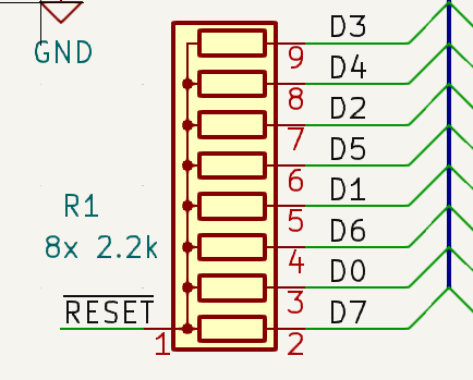
The \(\overline{\text{RESET}}\) signal (pin 8 of U1) in the system meets the requirement of being low during reset and becoming high in the first clock cycle after reset. Through experimentation, changing the resistors R1 to 8×2.2k, with the common end connected to pin 8 of U1, allows the system to operate normally at 12 MHz with 74HC devices, HY62256ALP-70, and AM27C256-55DC. However, it fails to function properly at 16 MHz (14 MHz is untested because of there is no 14 MHz crystal oscillators on hand). The results are same with AS6C62256-55PCN.
It’s worth noting that using a dedicated higher-output-drive NOT gate such as 74LVC1G04, connecting \(\text{RESET}\) signal (pin 9 of U1) to the gate’s input, and connecting the common end of R1 to the gate’s output would be a better solution.
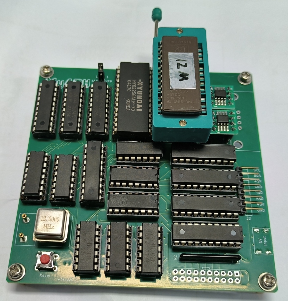
To further improve the speed, experiments show that the RAM can be changed with IS61C256AH-20N (or a faster version). With IS61C256AH-20N, AM27C256-55DC and 74HC devices, the system can operate normally at 16 MHz. Serial port communication can be established at a baud rate of 9600 using the ROM image file My4TH-nfd-rom_8MHz_v1.4.bin provided by the original author.

Due to the DIP version of IS61C256 being a narrow-body (7.62 mm) device, modifications were made to the RAM socket on the PCB for compatibility. The modified project (including changes on the pulling resistors) can be downloaded here. This version also includes a few other changes, such as the use of a 4-layer PCB, changing the power input port to USB Type-C, and replacing some components with surface mount devices.
The DIP version of IS61C256 has been discontinued, but surface mount versions (SOJ and TSOP packages) are still in production. If you wish to use currently produced DIP device as of Dec 2024, consider AS7C256C-15PCN.
SMT Version
To further reduce the size, a 60mm x 70mm SMT board was created. This version uses TSOP-packaged IS61C256AL-12T(L)I or CY7C199(L)-15ZC RAM, TSSOP-packaged logic circuits, and adds a 74LVC1G04 for pulling resistors and a CH340N for USB-to-serial conversion. The project can be downloaded here.

Troubleshooting
If the system is not functioning properly at 16MHz, focus on checking the following issues:
- Power supply voltage: Ensure the \(V_\mathrm{cc}\) voltage is above 4.8V. Note that due to the use of a reverse current protection diode (D3), powering the SMT board via the USB interface may result in insufficient system voltage. Using a USB hub with external power can resolve this issue. If simultaneous use of the USB interface and external power is unnecessary, you can short-circuit diode D3. Using 74AC161, LV161, and LV08/AC(T)08 may also help.
- Replace HC541/HC574 chips: Try using HC541/HC574 chips from different manufacturers. Chips from smaller Chinese manufacturers may work better than those from TI/Nexperia (though TI’s HC139 performs better).
- Replace ROM: Differences between individual ROM chips may cause the system to malfunction, especially at lower supply voltages. Compared to the AM27C256-55DC, the AM27H256-45/35DC allows the system to operate at lower \(V_\mathrm{cc}\).
- Try running at lower speed (e.g., 8MHz). if still not working, check soldering.
Operating current for reference (\(V_\mathrm{cc}=5\mathrm{V}\), running at 16MHz): 90mA(running)/15mA(pressing RESET) with AM27H256-35DC and IS61C256AL-12TLI, 150mA(running)/70mA(pressing RESET) with AM27C256-55DC and IS61C256AH-20N.