|
|
|
|
|
|

Changes last made on: Sunday March 14, 1999
This page provided by Don Hill (KE6BXT)
[email protected]
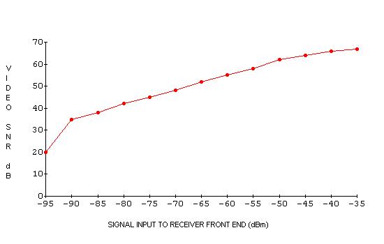
The following information is to help in calculation of RF power and antennagain needed to properly access the new input. Line of sight is assumed in thefigures. Threshold (the point were most of the sparklies are gone) is -90 dBminto the front end (filter + preamp at the antenna). Antenna gain is 10 dBdin most directions, south Orange County area has a few dB reduction due tothe tower blockage. So let us assume that we want some fade margin, about10 db minimum this will give a -90 dBm minimum target signal level thatwe need to get from your QTH to the hilltop. Use a map to find Santiago Peakand get the distance to the repeater and use the chart to find path loss indB. Now add your TX power in dB (chart provided), subtract line loss and addantenna gain this should help to better provide you with equipment andantenna requirements you will need. Example: TX power +30 dBm (1 watt) lineloss 1 dB antenna gain +24 dB path loss -127 dB 30 miles this givesa -74 dBm level at the hilltop.
|
|
|
|
|
|
Changes last made on: Sunday March 14, 1999
This page provided by Don Hill (KE6BXT)
[email protected]