9MHz IF Filters
|
The radio will have selectable IF
filters for 2.4kHz and 5kHz bandwidths.
The first will be an INRAD 8-pole SSB filter and the latter a 4-pole crystal filter.
SSB Filter Module The 8-pole crystal filter is a bit
expensive for a kit, but I had one and wanted to use it in a design. The impedance of the filter is 500 Ω
// 30pF. I used an L network to
impedance match each side of the filter with the actual termination
impedances. For the filter response measurement
below, I used 5% resistors to impedance match the filter to my 50 Ω
analyzer. The slight impedance mismatch
is causing passband ripple and creates ~28dB of
loss. I’ve had better results with L/C
matching networks but I didn’t save a picture.
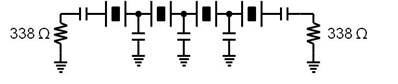
Cohn Filter A 4-pole crystal filter using 9MHz
crystals was created using the architecture below. The crystal parameters were determined
using the G3UUR method. With these
parameters, I used AADE filter design software to create a Cohn Filter for my
AM filter. The terminating impedance
of the filter is ~338 Ω with all capacitors being 52pF.
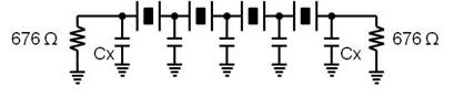
I decided to impedance match the filter
with a simple L-network rather than the matching network proposed by the AADE
software. To start, I converted the 52pF end capacitor and 338 Ω load
resistance into its parallel equivalent combination at 9MHz. (676 Ω // 26.2pF). Where Cx is
26.2pF and all other capacitors are still 52pF.
Finally, I had to transform the 676 ohm
impedance to the actual impedance seen on each end of the filter. I used the L-network equations to find appropriate
L/C values. At this point, I was able
to combine Cy from the L network with Cx from my
filter into a single capacitor value.
For the filter response measurement, I
again used 5% resistors to impedance match the ~338 Ω filter to my 50 Ω
analyzer. Again, it creates ~28dB of
loss due to matching networks.
|