 |
The IC-PS35 "bathtub" modular switching power supply is an accessory for the IC-751 and IC-751A. Variants of the IC-PS35 are used in the IC-PS30 system power supply, and also in the IC-761 and IC-765. The voltage and current-protector adjustments are identical for all three versions, with the exception of a difference in the adjustment-point designations.
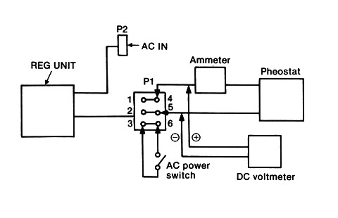
DC voltmeter, 0 ~ 15V
DC ammeter, 0 ~ 30A
Power rheostat, 0 ~ 2Ω 300W, with 0.55Ω, 0.69Ω and 1.38Ω set points marked
| ADJUSTMENT | ADJUSTMENT CONDITIONS | MEASUREMENTS | VALUE | ADJUSTMENT POINT | |||
|---|---|---|---|---|---|---|---|
| UNIT | LOCATION | UNIT | ADJUST | ||||
| OUTPUT VOLTAGE | 1 |
|
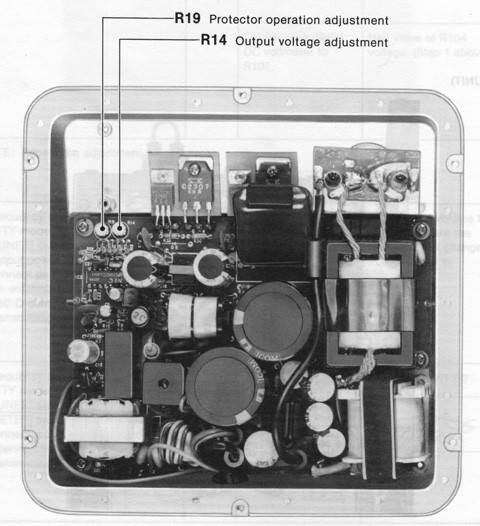
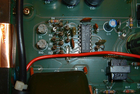
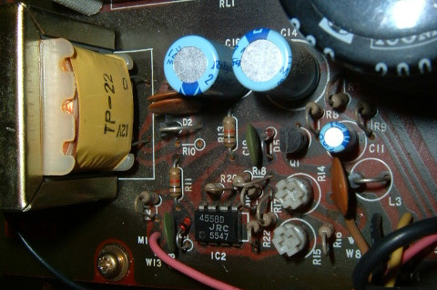
IC-765 REG, IC-PS35 (Fig.2) |
Connect a DC voltmeter as shown in Figure 1. |
13.8V | IC-765 REG, IC-PS35 |
R14 |
| IC-PS30 REG (Fig. 3) |
IC-PS30 REG |
R5 | |||||
| CURRENT PROTECTOR OPERATION |
2 |
|
IC-765 REG, IC-PS35 (Fig. 2) |
Adjust pot. until output voltage just drops. |
IC-765 REG, IC-PS35 |
R19 | |
| IC-PS30 REG (Fig. 3) |
IC-PS30 REG |
R10 | |||||
| IC-PS30 VOLTAGE SCALE |
3 |
|
IC-PS30 METER SWITCH (Fig. 4) |
Connect a DC voltmeter as shown in Figure 1. |
IC-PS35 meter: 13.8V | IC-PS30 METER SWITCH |
R4 |
| IC-PS30 CURRENT ZERO |
4 |
|
IC-PS30 METER CAL (Fig. 5) |
Observe IC-PS30 meter. |
IC-PS30 meter: 0A | IC-PS30 METER CAL |
R15 |
| IC-PS30 CURRENT SCALE |
5 |
|
IC-PS30 METER CAL (Fig. 5) |
Connect a DC ammeter as shown in Figure 1. |
IC-PS30 meter: 20A | IC-PS30 METER CAL |
R14 |
|
|
 |
 |
 |
 |
| Description | Icom Part No. |
|---|---|
| Chassis connector | 6510003760 |
| Pins for connector | 6510003790 |
| Cable connector | 6510013170 |
| Pins for cable | 6510007650 |
Copyright © 2005 A. Farson VA7OJ/AB4OJ. All rights reserved.
Based on e-mail discussions with Ralph Marrs K5JN and Walt Szachara W2OKF.
Last updated: 06/15/2018.