|
|
 |
The IC-7610
block diagram is provided for
reference. (Service manual, pp. 8-2, 8-3. Excerpt courtesy Icom Inc.)
The block diagram (TUNER Unit) in the IC-7610 service
manual shows an RF coupler in the signal path between the harmonic filters and
the reflectometer. This coupler has 30 dB coupling loss and feeds the RFMON line
via a 24 dB fixed attenuator. The RF MON line is identical to the PW2FB (PW2
Feedback). line on the MAIN Unit, and feeds the SUB ADC driver via a 12.5 dB
fixed attenuator. (p. 8-2)
Looking at the ALC RCA jack and ACC2 socket on the right side of p. 8-3, Pin 5 is switched via a relay between EALC and PW2FB. At the same time, EALC is still brought out to ACC2 Pin 5 (ALC). There are 7 modes of operation:
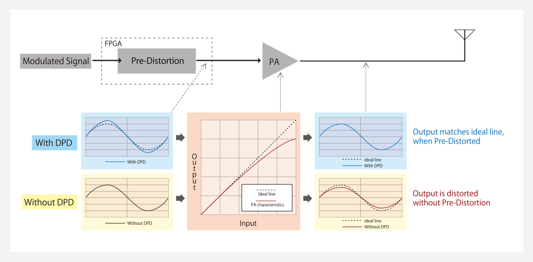
PW2 with OPC-2501 or equivalent DPD cable connected and DPD enabled in IC-7610: The ALC RCA jack is re-routed to PW2FB, whilst the ALC line (required for safe operation of the PW2) is connected to EALC via ACC2 Pin 5. ALC goes to the ALC comparator.
.PW2 with DPD disabled: DPD cable not connected, ALC via ACC2 Pin 6 to EALC.
PW1: DPD disabled, no DPD cable, ALC via ACC Pin 5 to EALC, PW2FB not driven.
Non-Icom amplifier, no DPD, ALC via RCA SEND jack to EALC.
Barefoot, DPD enabled. ALC direct from internal ALC comparator, RFMON to PW2FB.
Barefoot, DPD off: ALC as for 5, PW2FB not driven.
Theoretical non-Icom amplifier with sampling coupler. Similar to #1, but ALC RCA jack is connected to amplifier’s coupler output, ALC (0…-4V max.) connected to ACC2 Pin 5.
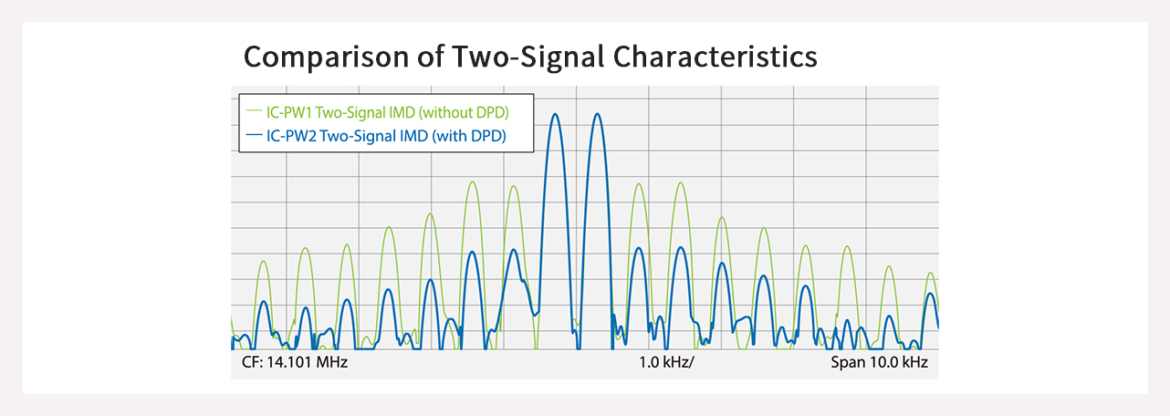
In broad terms, it looks as if two DPD modes will be possible: 1: Barefoot via RFMON. 2: Amplifier sampling, via PW2FB (which receives the RF sample via the ALC RCA jack in DPD active mode with PW2 connected).
Copyright © 2017-2023 A. Farson VA7OJ/AB4OJ. All rights reserved. Images: contributors as noted.
Last updated: 12/18/2023
![]()