 |
|
|
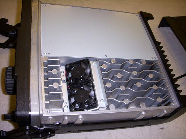
Fig. 1 shows the IC-7200 with the top cover removed. The redundant fans and the heatsink casting are visible. The only penetration in the top of the radio pulls air into this space, which is sealed off from the compartments housing the boards. The control board is on the top left side of the radio, and is covered by another panel which is sealed and gasketed. The solid, die-cast chassis accounts for a considerable portion of the radio's 5.5 kg (12.1 lb) weight.
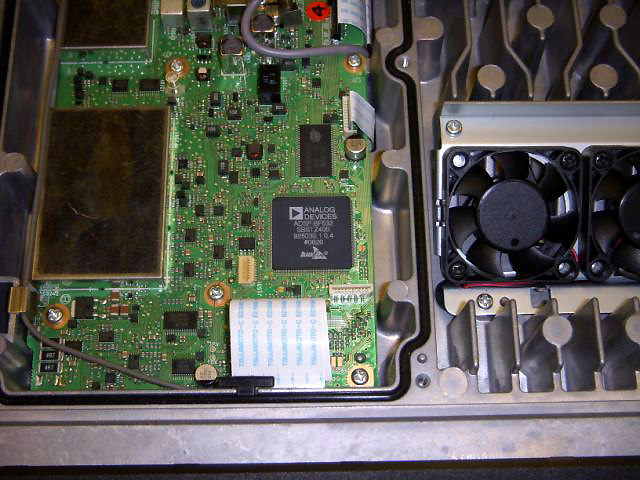 |
Fig.2 shows the control board in the top left side of the radio with the ADI Blackfin processor (ADSF BF532). Note the O-ring gasket that runs around this compartment.
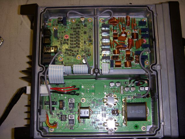 |
Fig.3 shows the bottom cover of the radio removed. Again, there is an O-ring that runs entirely around the bottom cover panel, and the boards are housed in different compartments with the PA being directly under the heatsink casting. The circuit boards are even isolated from the front panel in their respective compartments.
There is no air-flow through the PA compartment, as the boards are mounted (and thus thermally coupled) to the aluminum casting that runs through the radio (all the silver shown in the picture). Although there are some penetrations in the rear of the radio to accommodate jacks, they are tight and the boards are mounted to the top of these compartments so any water intrusion should stay away from the boards.
The IC-7200 is clearly not waterproof (immersible). There are still case penetrations, but the radio is certainly protected from exposure to rain, dust or sand in normal operating conditions. If water (or coffee) entered from the top it would just dribble out the back. It may cross some jacks and if it managed to enter the radio, it would just sit inside on the bottom cover. A little operating would dry it right out!
After sitting powered up at Dayton all day, the IC-7200 was only slightly warmer than when first turned on. There was no identifiable warm spot on the radio.
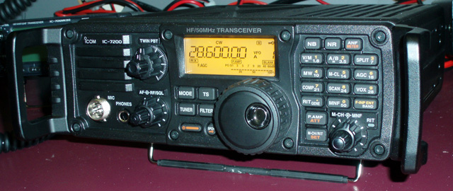 |
Fig.4 is a close-up of the front showing the rubber coated bail on the bottom. The radio stays very “planted” with this bail on the laminate countertop.
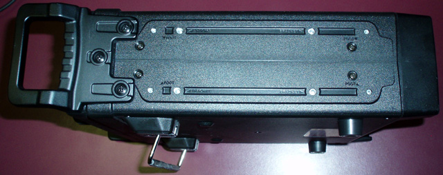 |
Fig.5 shows the right side panel of the radio with the optional front handles installed. The screw mounts for the optional mobile bracket and feet are clearly visible. The opposite side panel has holes for the mobile bracket and carry handle.
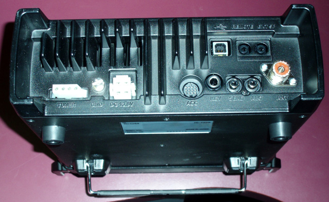 |
Fig.6 shows the rear panel of the radio. Most of the jacks are identical to those on other Icom radios. The CI-V (REMOTE) jack is still present despite the USB connection. The serial bus design of the CI-V is a great solution for interfacing to accessories and multiple radios off a single port. The USB offers both computer control and audio support. The angled aluminum castings along the rear edges form the “rear bumper”. The radio can be set on this bumper and will stand upright. The bumper extends far enough that with a right angle PL-259 connector the radio could be operated while standing vertically. The front handles offer similar protection at the front of the radio and the ability to stand it on the face while attaching cables to the rear.
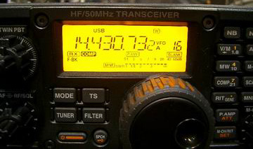 |
Fig.7 is a detail view of the radio's LCD display screen.
Copyright © 2007-2008 A.Farson VA7OJ/AB4OJ. All rights reserved. Last updated: 06/16/2018.