 |
| Band, MHz | Band Voltage |
|---|---|
| 10 | 0V |
| 50 (unofficial) | 1.0 ~ 2.0V |
| 28 & 24 | 2.0 ~ 3.0V |
| 18 & 21 | 3.0 ~ 4.0V |
| 14 | 4.0 ~ 5.0V |
| 7 | 5.0 ~ 6.0V |
| 3.5 | 6.0 ~ 7.0V |
| 1.8 | 7.0 ~ 8.0V |
All Icom HF and HF/VHF transceivers (except for the IC-701) provide an analogue band-selection voltage in the range 0 ~ +8V. This voltage serves to bandswitch external accessories such as the IC-2KL and IC-4KL amplifiers, the IC-AT150, IC-AT100 and IC-AT500 autotuners and the EX-627 antenna selector.
The 18 and 21 MHz bands are grouped together, as are the 24 and 28 MHz bands. Zero voltage corresponds to 10 MHz. The 50 MHz band is not officially supported.
Table 1 (above) gives the band voltage range for each band.
Note: The band voltage follows the transmit band selection. When operating split, the band selected on the transmit VFO determines the band voltage (and thus the band selection in the external equipment), even if the transmit and receive VFO's are on different band. This is true whether the transmit VFO is active (assigned to the tuning knob) or not.
Icom transceivers and accessories fitted with DIN ACC(1) and ACC(2) sockets provide the band voltage, +8V reference voltage and ground return on ACC(2). Earlier Icom products fitted with the 24-pn Molex ACC socket also provide these interconnections. Adapter cables are required to interconnect transceivers and accessories with different accessory sockets.
Icom used to offer the OPC-118 adapter cable (female 24-pin Molex to male ACC1 & ACC2), and the OPC-126 (male 24-pin Molex to female ACC1 & ACC2).
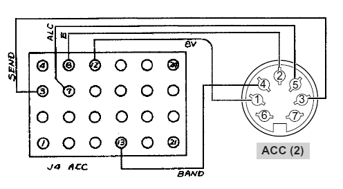
If you wish to make up your own OPC-118 to connect an IC-756Pro3 to an IC-2KL, for example, the connections are as follows: The ACC(2) plug is a male 7-pin DIN, and the accessory plug for the 2KL is a 24-pin Molex (male if plugged into the IC-2KL, female if plugged into the IC-2KL control cable.) Fig. 1 is a wiring diagram, and Table 2 gives the interconnections. (Note: The ALC line is mandatory when using the IC-2KL or IC-4KL.)
The corresponding pinouts for the 13-pin DIN ACC plug used with the IC-706 series, IC-7000, IC-7100, IC-7410 and IC-9100 are also given in Table 2. This will facilitate making up a suitable cable to connect the IC-2KL to one of these radios. Note: In some cases, the transceiver's BAND voltage line must be enabled (typically by bridging two pads on the main board).
The Icom OPC-599 adapter cable adapts a male 13-pin DIN plug to female 8-pin (ACC1) and 7-pin (ACC2) sockets.
The correct male 24 pin Molex connector body and pin contacts are available from Mouser Electronics as P/N 538-03-06-2242 and 538-02-06-2103, respectively. They are also available from DigiKey as P/N WM1229-ND and 02-06-2101-ND, respectively. (Contributed by John, W5JMN)
|
|
| ACC(2) Pin | 13-Pin ACC Pin | Molex ACC Pin | Description |
|---|---|---|---|
| 1 | 1 | 12 | 8V BAND REF |
| 2 | 2 | 8 | GND |
| 3 | 3 | 3 | SEND |
| 4 | 5 | 13 | BAND 0 ~ 8V |
| 5 | 6 | 7 | ALC |
| 6 | NC | NC | NC |
| 7 | 8 | NC | ACC +13.8V |
Copyright © 2007-2016, A. Farson VA7OJ/AB4OJ.
Last updated: 09/21/2016