The SuperHet
This is my first attempt at building a Super Heterodyne Receiver and will most likely serve as a test bed. The design is loosly based on the ATS-4 by KD1JV. It uses 2-SA602 mixer chips along with a 4-pole crystal filter. For the audio filtering section the Op-Amps are LMC662.

Here's the schematic minus the VFO
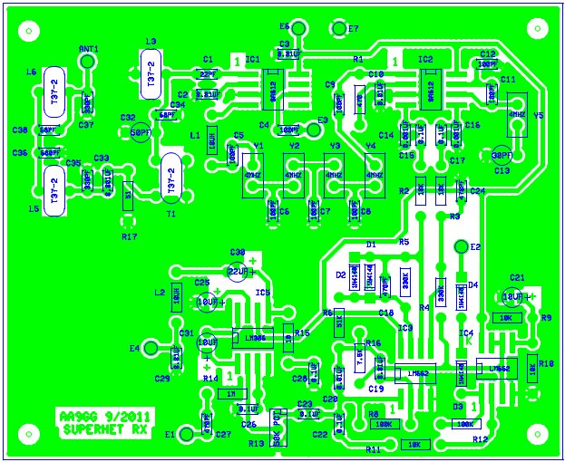
Here is the current PCB I'm working on. The PCB measures 4.5" X 5.5". Note that it is single-sided and will be made using the toner transfer PCB method.
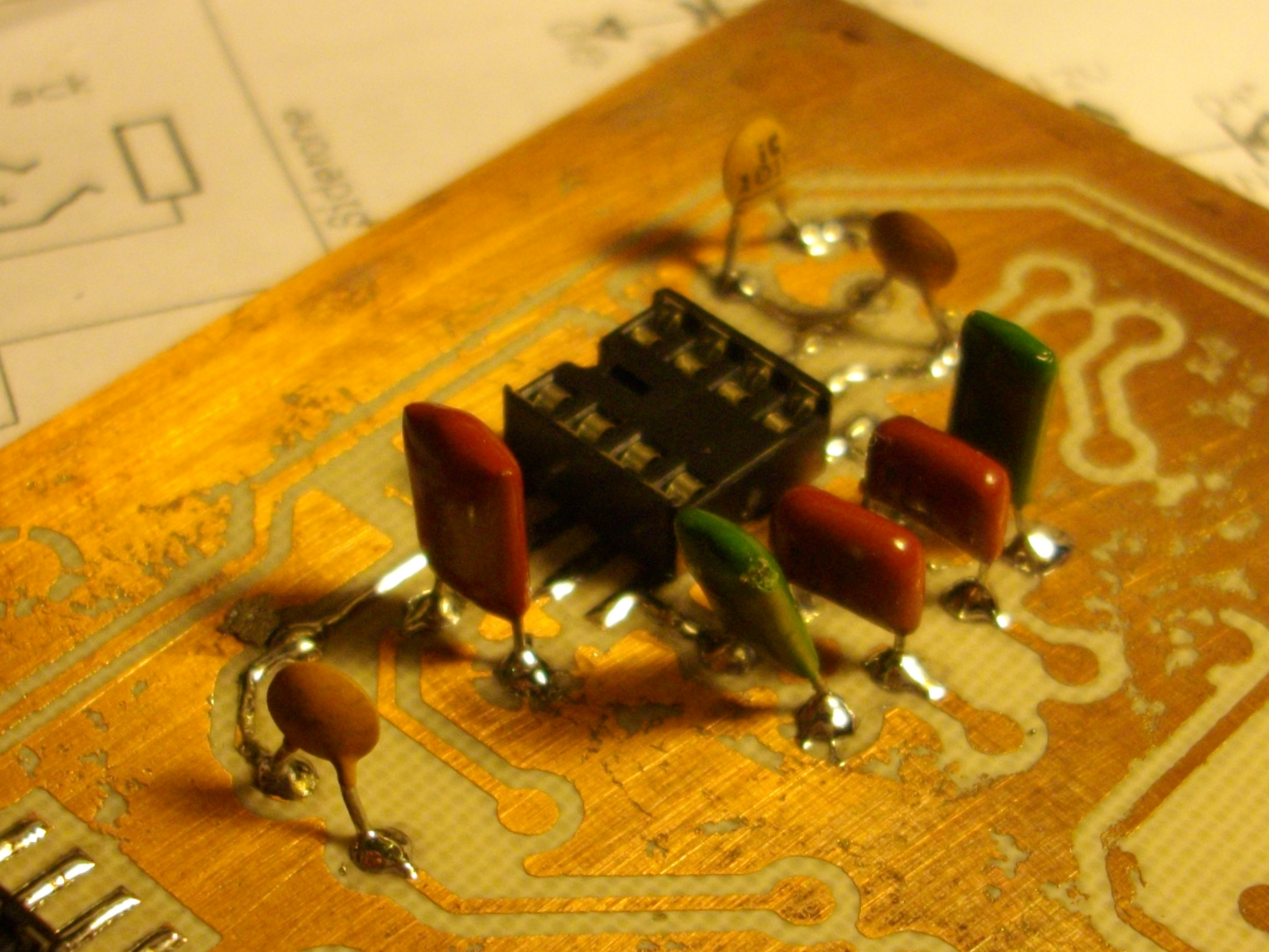
What is unique about this design is that all components are thru-hole and placed like SMT parts on the board. NO HOLES TO DRILL (except for mounting). You can bend a little foot on the part, or just solder directly to the pad. For the ICs, You take IC sockets and fold the legs out so it sits flat,spread-eagle, on the pads. I kinda' like this method of construction, because you DON'T have to worry about drilling holes. Also parts can easily be swapped out for experimentation.
Here is the final schematic and PCB artwork for downloading and "rolling your own"
The zip contains 1:1 PCB artwork, schematic, parts placemant, and a parts list. It's been "flipped" and is ready for use with the toner-transfer method. You could also use the photo method if you prefer. Either way, just make sure you when you print the PCB to use no scaling.
Let the games begin....
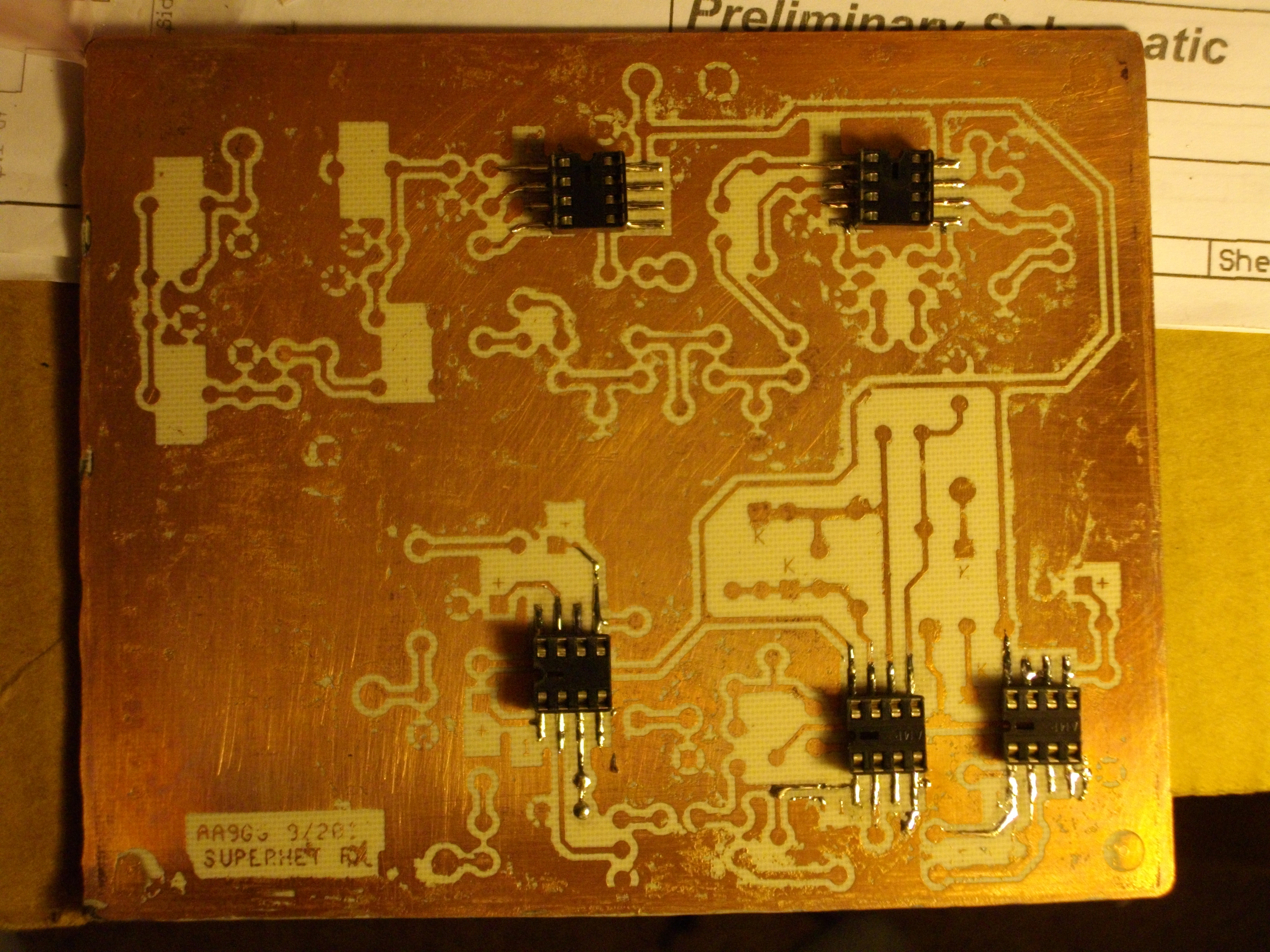
Here's the pcb with the ic sockets mounted on it. The pcb didn't turn out too bad. I have a few minor breaks to fix and the ground plane is a little rough, but it's usable.
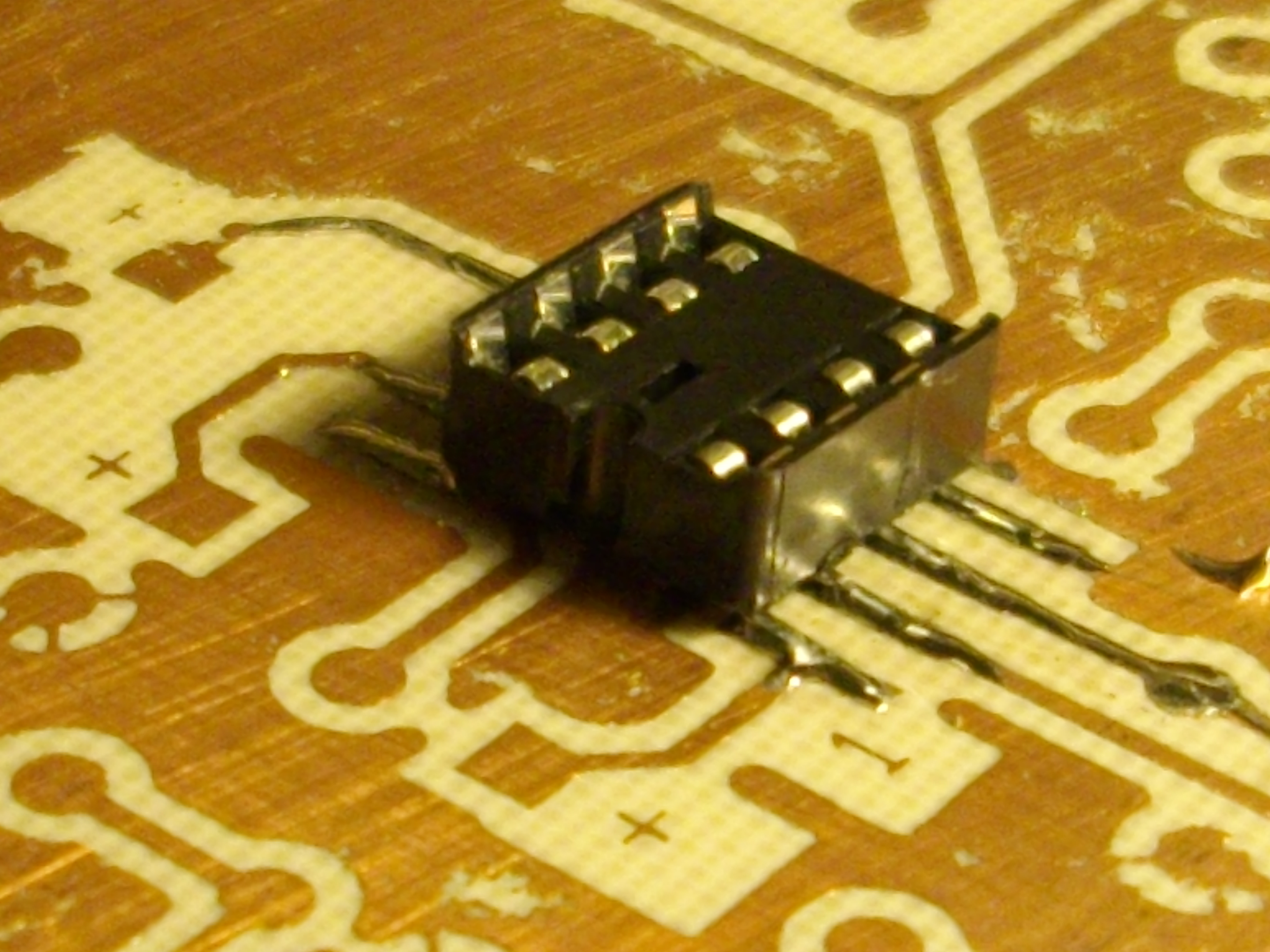
This is a little closer up detail on how the ic sockets are mounted "spread-eagle". This was/is a GREAT idea!!!
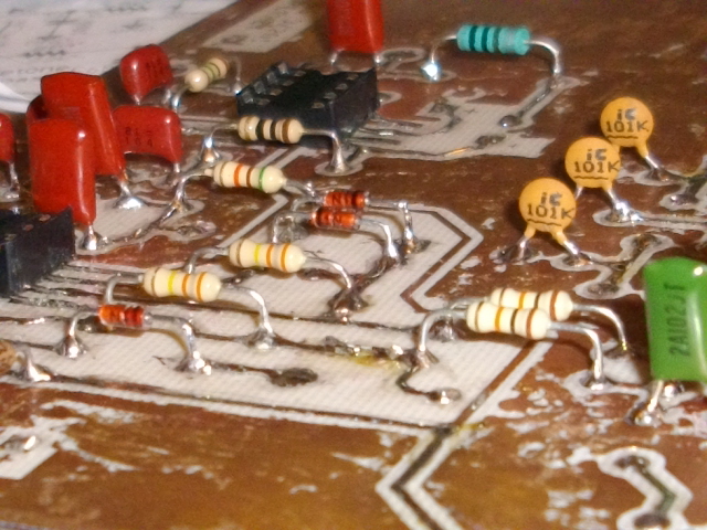
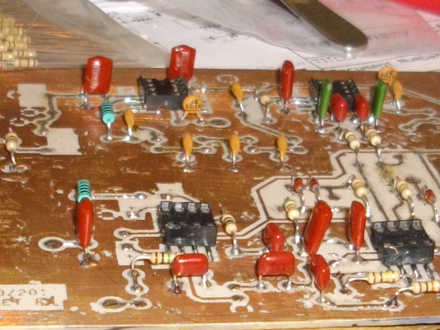


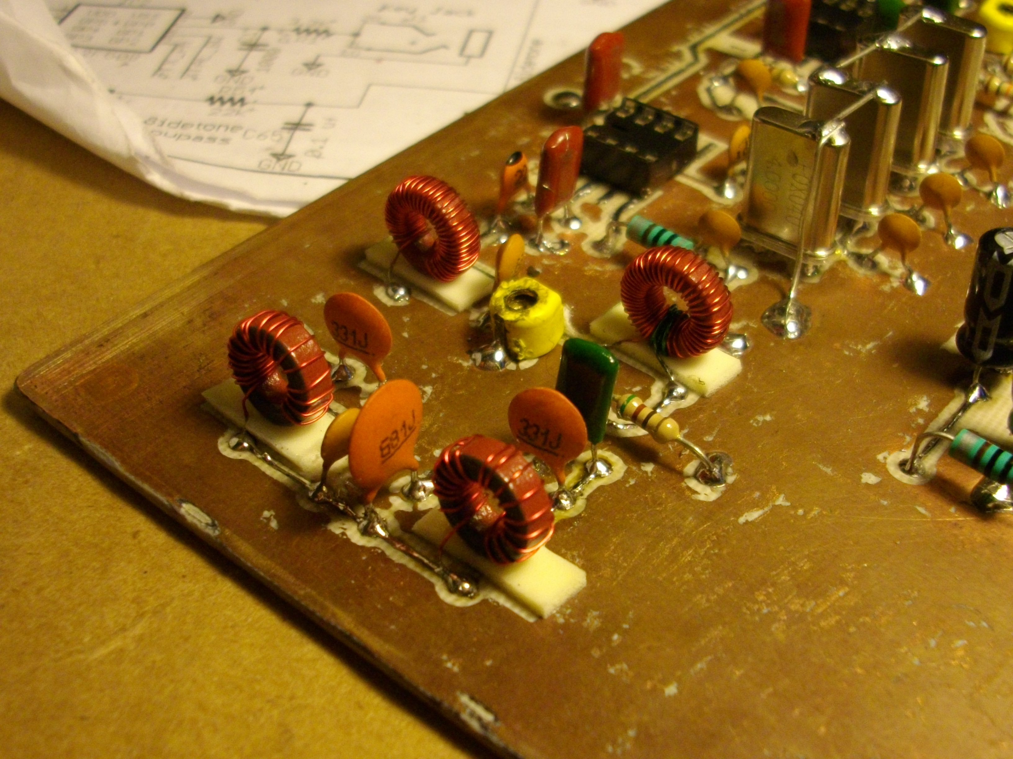
Some shots on how the components are mounted. I bend the leads, clip them off to about 1/8" long and then simply solder in place. Just about done "stuffing" the board. Now I just have to wind the 4 toroid transformers.
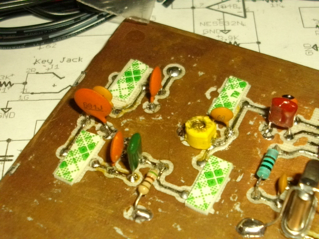
I like to use double-sided foam tape to hold the toroids in place on the PCB. It will help to help stabilize them and take the stress off the wires.
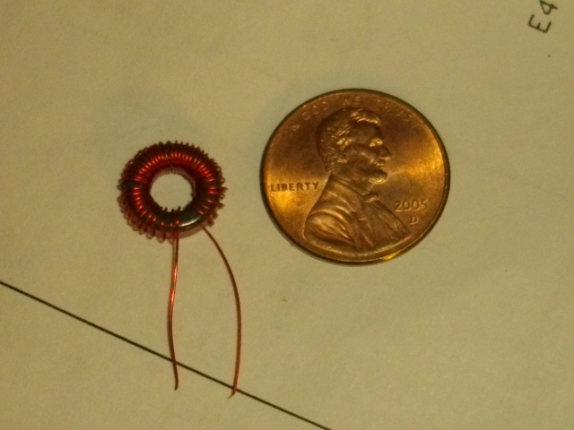
Yes...40 turns of #30 AWG will fit on the tiny T37-2 Toroids.
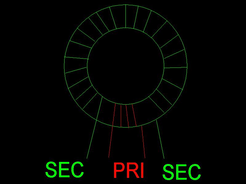
Note how T1 is wound. The primary is wound in the gap between the turns of the secondary. It is ok to over-lap if need be.
On the PCB, the Primary is the lower set of pads and the Secondary is the upper set of pads.
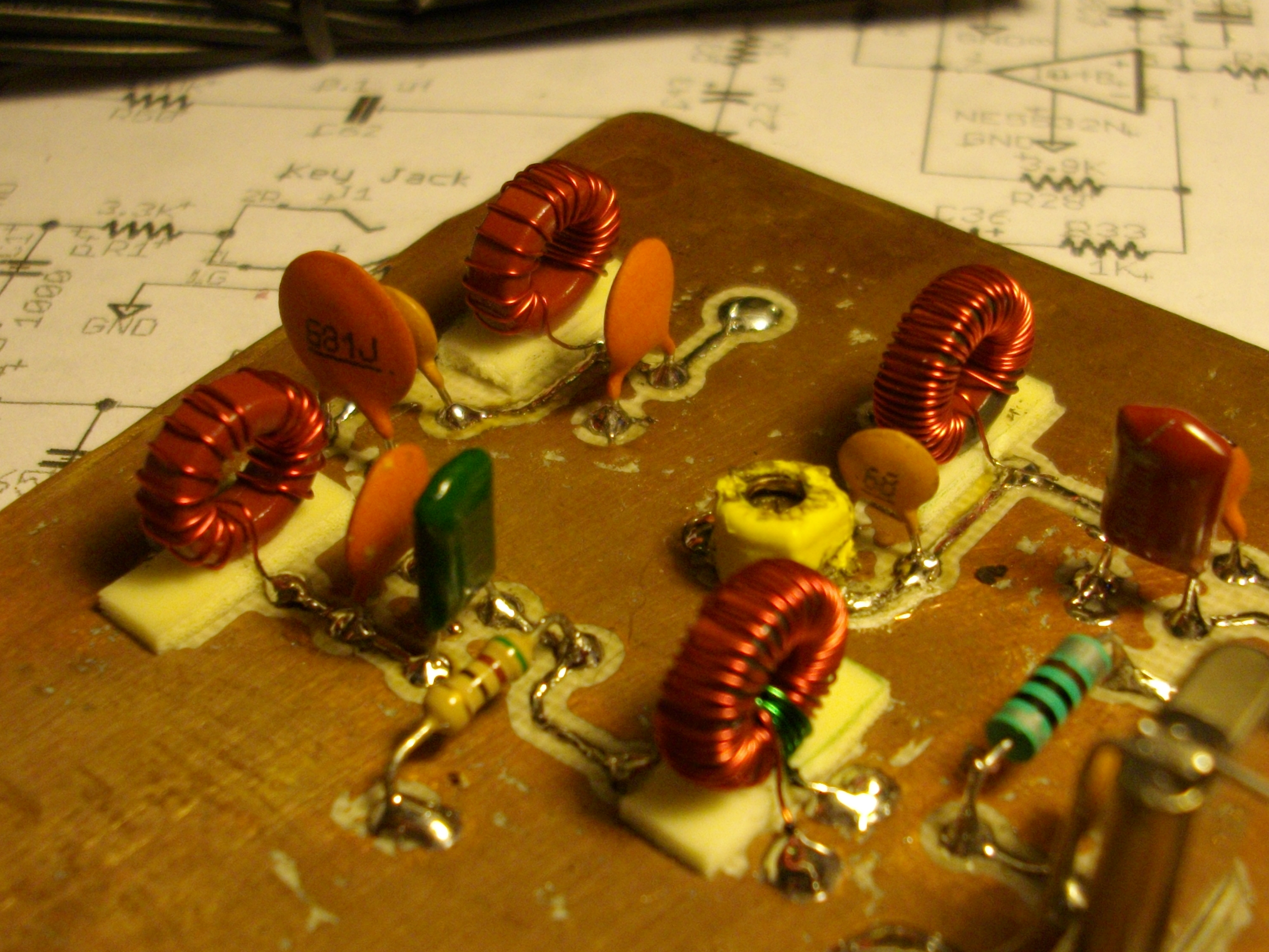
All toroids are wound and mounted (I guess I could have used shorter pieces of foam tape). The values on the schematic are for a 40m front-end.
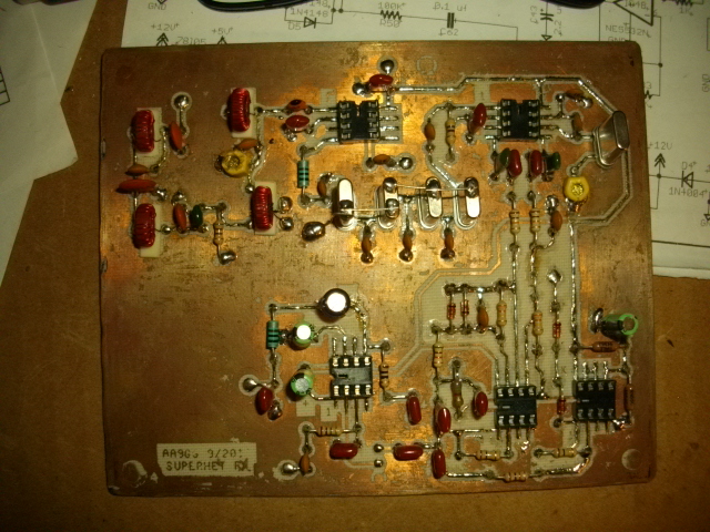
Well...there we have it. Next step is to apply voltage and check the supply lines before I plug in any ICs. Then I guess I'll have to get the VFO portion of this project rolling...
Are you building along? Comments? Questions? Drop me an Email
Watch this space as progress continues.....

Back to QRP Build Page
Last updated : Tuesday, September 13, 2011 10:24:51 PM
Website created and maintained by AA9GG