(magtherm.htm)
Further Results of FGM-3h tests and comparisons,
January - February 2000
Last changed April 27 2003
(Some links updated)
"Lab notebook" web page of Darrel Emerson (continued)
See also:
Fluxgate Magnetometer tests: FGM-3h (December 1997)
Email to Darrel Emerson:
[email protected]
These tests describe measurements made an FGM-3h fluxgate
magnetometer and its associated electronics;
the effect of temperature changes on the magnetometer
system, and residual long term drifts over a period of about 2 months
were studied.
The sensors are
made by Speake & Co., supplied in the USA by
Fat Quarters
Software and Electronics. More information may be obtained
from Erich Kern. I have no personal
connection with either company. The magnetometers are particularly
sensitive, and are designed to measure small fluctuations in the
geomagnetic field. The results presented here are of my entire system,
including home-made electronics for DC voltage stabilization for the
magnetometer, and the data acquisition hardware and software.
The drifts I detect may come from this supporting electronics rather
from the magnetometer itself; I'm still looking into that.
- Introduction
- General description of setup
- Measurements of Magnetometer drifts due to temperature: daily averages,
corrected data, and a comparison with USGS data
- Conclusions
The earlier notes,
Fluxgate Magnetometer tests described the Speake FGM3 series of
fluxgate magnetometers, intended to be used to measure small variations
of the geomagnetic field, or other small magnetic effects. The FGM-3h in
particular is very sensitive - so sensitive that it will saturate if
subject to the full geomagnetic field; in normal use, the FGM-3h is aligned
E-W, at nearly right angles to the main geomagnetic field. Used in this
way it is sensitive to the "Y" component of the earth's field. Fluctuations
in the "Y" component are almost exactly proportional to variations in
the "D" term, or the magnetic declination. Any book about the geomagnetic
field will give the details.
These earlier measurements showed that, with reasonable care, the residual
noise or error on measurements with the FGM-3h of magnetic activity,
over a few hours, can be less than 0.5 nT (or 0.5 gamma) rms. This is provided that
slow drifts, with a timescale of several hours or longer, can be ignored.
In the earlier measurements, the dominant cause of drift in magnetometer
output was found to be temperature changes. I do not know how much
of this temperature sensitivity is a feature of the magnetometer itself,
or of my own electronics that supplies power to the magnetometer, and
measures the pulse frequency from the sensor.
This document describes
the result of monitoring the temperature of the FGM-3h magnetic sensor,
and using
the temperature measurements to derive a correction for measured magnetic
field readings. This correction is quite successful. There are still
weak residual long-term drifts in the output of the sensor,
but sufficiently small and slow
that for most purposes they will be insignificant.
The general measurement scheme is exactly as described in the earlier
Fluxgate Magnetometer tests document. The FGM-3h magnetometer
requires a stablized 5 volt supply, and gives a stream of TTL-compatible
pulses, whose period is approximately proportional to the magnetic field.
Corrections for slight non-linearity of this relationship is discussed
in the earlier document. For zero field (i.e. with the magnetometer aligned
exactly along the geomagnetic E-W axis) the pulse frequency is approximately
60 kHz. The responsivity was measured and plotted in the earlier test
document, but is around 1 Hz change in frequency for a 1 nT change in
magnetic field.
For the earlier measurements, the output of the magnetomete was fed to
a frequency counter (an Optoelectronics model 3000) with an RS232 interface,
so that results could be logged to a computer (a dedicated 286 laptop).
The counter was set to a gate period of 10 seconds, so the frequency of
around 60 kHz could be measured to about 0.1 Hz precision. For the
measurements described here, a circuit using a Basic Stamp II was used.
The schematic (which is more complicated than it needs to be)
of the Basic Stamp II data acquisition system is
available
here. Some "tricks" were necessary to get
the best out of the Stamp circuit - including making it monitor its own
temperature, with a thermistor, and to apply corrections accordingly.
One day, I'll write those details down in another web document.
Throughout the measurements described
here, the Stamp circuit and the original Optoelectronics counter were
both collecting data simultaneously, logging data into independent
laptop computers. Although data from the Stamp circuit were used for
the analysis, both sets of data were regularly compared, and
were found to be almost indistinguishable from each other.
The FGM-3h magnetometer used in these measurements is fairly well isolated.
It is placed inside a vaccum (thermos) flask, which contains capsules of
water to give thermal intertia. The screw-top of the thermos flask is
replaced by a 2-inch styrofoam plug, of which about 1 inch pushes tightly into
the flask. This gives better thermal isolation than the original screw top,
and conveniently allows wires to the magnetometer, and to a temperature
sensor probe, to enter the flask. The temperature probe is a thermistor,
whose resistance is measured by the Stamp II microcontroller. The calibration
from thermistor resistance to temperature is performed by the 286 computer.
Long, thin wires were used to the
temperature and magnetometer sensors, to reduce heat conduction to and from
the outside world. This vacuum flask is inside a styrofoam
picnic container, which is packed with freezer gel bags, to give more
thermal inertia. This styrofoam container is placed inside a second
styrofoam container, made of 2-inch thick styrofoam sheets. Inner and
outer surfaces of the styrofoam boxes are coated with aluminum foil to reduce
radiation transference of heat. The outer box is placed in a fairly
secluded corner of my living room, against 2 outer stone walls of the house.
All this
thermal isolation quite effectively damps out the daily temperature
variations that would otherwise badly affect the magnetometer readings.
However, the inside temperature of the vacuum flask does change slowly,
following the mean daily temperature, but with a time lag of a couple of
days.
Magnetometer and temperature readings inside the flask are recorded
by the Stamp II microcontroller every 10 seconds. The 286 computer calibrates
and averages both magnetic and temperature data, recording the averages
approximately every 2 minutes. The measurements described here are from
the first 50 days of the year 2000.
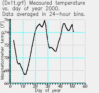
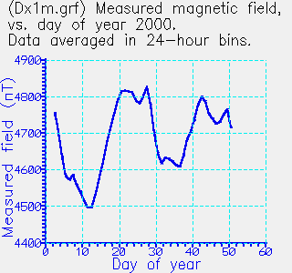
Below I show plots of my measured magnetic field, averaged in 24-hour blocks,
for the first 50 days of the year 2000. I show matching plots of the
temperature measured at the magnetometer; the correlation between changes
of temperature and apparent changes in magnetic field is astoundingly
good. The apparent change in field is entirely an instrumental effect,
coming either from the magnetometer itself, or from the associated
electronics. Because the apparent field change and temperature track
each other so well, I believe that electronics outside my thermal
enclosure cannot be responsible. More work is needed to locate the cause
of this drift.
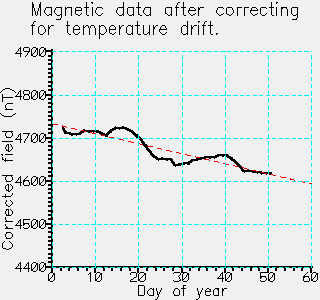
I have used the measured temperature changes to correct the measured
magnetic field, assuming an empirical factor of 46 nT/deg F. Figure 3
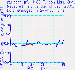
shows the corrected values. Figure 4 shows measurements over the
same period from the USGS Tucson Magnetic Observatory.
Although the steady drift in the USGS data (+0.5 nT/day) is smaller
than my own (-2.3 nT/day), the residual rms noise in these daily
averages, after subtracting the linear drift, is nearly identical in my
own measurements to those from the Tucson Magnetic Observatory - i.e.
14 vs. 15.3 nT.
The plot below shows the temperature measured at the magnetometer,
for the first 50 days of the year 2000. The temperature was measured
every 10 seconds, but has been averaged over 24-hour blocks,
0h UTC to 2400h UTC for each of the 50 days.

The plot below shows the magnetic field measured with the FGM-3h
magnetometer. The data have been averaged into 24-hour blocks.

The plot below shows the corrected magnetic field, after subtracting
a correction for temperature drifts. Changes in temperature were
scaled by 46 nT/deg F to derive the correction.
The straight line is a least squares fit to the data, and has a slope of
-2.3 nT/day. The rms deviation of the data from that straight line is 15.3 nT.

This plot (below) shows data over the same period
taken from the USGS Tucson Magnetic Observatory.
The data are available with 1-minute sampling, but have been averaged
into 24-hour blocks to compare with my own measurements.
The straight line is fitted to the data, and has a slope of
+0.5 nT/day. The rms deviation from that straight line is 14 nT.
Note that, from standard models, the expect drift in the "Y" component
at my location (Tucson, AZ) and at this time of year is only
about -0.02 nT/day.

I've compared long term, day-to-day drifts in measurements from my
Speake FGM-3h magnetometer with variations in temperature at the
magnetometer. There is extremely good correlation. A simple correction,
subtracting [(T-72)*46] nT from the data, makes a substantial improvement.
There is a slow residual drift of -2.3 nT/day superposed on the residual.
I don't know what causes the steady drift, but apart from that the
residuals probably result from temperature variations of the electronics
I use to collect the data.
Compared to the USGS Tucson Magnetic Observatory measurements, I'm not
doing too badly. Their measurements show a much smaller drift of only
+0.5 nT/day, but the rms noise of deviations from the steady drift
is about the same magnitude (14 vs. 15.3 nT) on the USGS and my own data.
Finally, note that these measurements only show long term, day-to-day
drifts and noise.
Other measurements show that the short term noise of my FGM-3 h measurements,
over a period of a few hours, is less than about 0.5 nT. Fortunately,
most magnetic events of interest last from minutes to an hour or so,
so the residual long term drift is of little consequence.
Back to top of document
Fluxgate magnetometer tests: Calibration of the FGM-3h magnetometer
Darrel Emerson top page
 �
�


