
| Driving Light and Accessory Protector for Cars External devices on cars are an easy target for thieves. Or at least they were: this will keep the crooks away from your car. By Rick Walters |
One night recently, an acquaintance had a pair of quite expensive driving lights stolen from the front of his 4-wheel drive while it was parked in his driveway. For the thief, it was almost too easy - just unplug (or cut) the leads, undo a couple of mounting nuts with a shifting spanner and off you go. It's that quick!
This circuit is designed to protect your expensive driving lights and at the same time, give the prospective thief quite a scare. As soon as the power lead to the light is cut or disconnected, either the car alarm will be set off or, if you don't have an alarm, a very loud siren will be triggered. If that doesn't scare the "low-life" away, nothing will.
One important feature of this unit is that it's automatically armed each time you turn the ignition off. After all, a thief detector isn't much use if you forget to turn it on. Similarly, the unit is automatically disarmed when the ignition is switched on.
Of course, this also means that the unit isn't foolproof - if a thief "hot-wires" the car, the alarm won't sound but then you'd have much bigger problems than just a pair of stolen driving lights.
How it works
Fig.1 shows the circuit details. As you can see, there is very little to it. The most complicated part is the circuitry involving IC1, which is used to mute the alarm after a short time to comply with noise pollution laws.
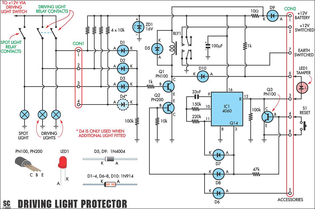
We have provided protection for up to four lights and these are connected to diodes D1-D4 via connector CON1. Basically, D1-D4 function as an OR gate. Normally, their anodes (A) are pulled low by their respective driving light filaments and so their commoned cathodes (K) are also pulled low via an associated 100kΩ resistor.
As a result, transistor Q1's base is also low and so this transistor and relay RLY1 are off.
Now consider the situation if one of the driving lights is disconnected. When that happens, the anode of the corresponding diode in the OR gate is pulled to +12V via a 10kΩ resistor which means that the diode is now forward biased. As a result, the commoned cathodes are pulled to about +11.4V and so Q1 now turns on (assuming that Q2 is also on) and activates relay RLY1.
Relay RLY1 is a double-pole double throw (DPDT) unit. As shown, its normally open (NO) contacts are connected to pins 2 & 7 of CON2. When the relay is activated, pin 2 is switched to +12V while pin 7 is pulled to ground. These outputs can be used to trigger the high-going or low-going inputs of an existing car alarm.
Alternatively, an external 12V siren can be connected between pins 2 & 7 of CON2 (or connected between pin 2 and ground).
Transistor Q2 (a PNP type) is included to ensure that the alarm remains off while the vehicle is being driven. As shown, this transistor is connected in series between Q1's emitter and ground. Normally, Q2's base is pulled low via a 10kΩ resistor and so this transistor is biased on.
However, when the engine is started, Q2's base is pulled high via the accessories line (pin 5 of CON2) and diode D6. This turns Q2 off and so Q1 and RLY1 are also off and the alarm is disabled. Turning off the ignition then automatically "arms" the circuit again.
Note that if Q2 were not included, the alarm would sound each time the driving lights were turned on.
Alarm timeout
IC1, a 14-stage binary counter, provides the timeout function. Normally, pin 12 (Reset) of this IC is held high via LED 1 and the 1kΩ resistor to the +12V rail. As a result, IC1 is held in the reset condition and its operation is inhibited.
When the alarm is triggered, Q1 and Q2 are both on and so Q1's collector is pulled down close to 0V (ie, ground). This in turn pulls the anode of LED1 low via diode D10, thus releasing the high on IC1's reset pin. Instead, the reset pin is now pulled down to 0V via a 100kΩ resistor and so IC1 now begins operating.
The RC network on pins 9 & 10 sets the frequency of the internal oscillator, while the selected binary output determines the alarm period. In this case, we have used the Q14 output at pin 3, which means that IC1 divides by 2 14 ie, 16,384).

Since we want the alarm to operate for about 90 seconds, this means that the oscillator frequency should be 16,384/90 = 182Hz. This frequency is set by the 33nF capacitor and 150kΩ resistor on pins 9 & 10.
At the end of the 90s timing period, pin 3 (Q14) of IC1 goes high and this pulls Q2's base high via D8. As a result, Q2, Q1 and relay RLY1 all turn off and the alarm stops.
But that's not all the high Q14 output does - three other events also take place. First, it turns on transistor Q3 via a 47kΩ resistor and this holds IC1's Reset (pin 12) low. Second, it pulls pin 11 high via D7, which stops the oscillator. And third, because Q3 is on, LED1 lights to show that the alarm has been activated - ie, LED1 functions as a "tamper" indicator.
When the wiring to the light has been reconnected, Q3 is turned off by pressing the Reset switch (S1). This releases the low on pin 12 and rearms the circuit.
Power for the circuit is derived from the car's battery (via a 1A in-line fuse - see construction). Diode D9 provides reverse polarity protection, while a 10Ω resistor and 100μelectrolytic capacitor provide supply decoupling. In addition, zener diode ZD1 is included to protect the IC from high-voltage spikes on the supply line (eg, when other equipment switches on and off).
Finally, diode D5 protects transistor Q1 by quenching the back EMF generated each time the relay switches off.
Building it
Building it is easy since all the parts are mounted on a PC board measuring 109 x 48mm (code 03109021). Fig.2 shows the parts layout.
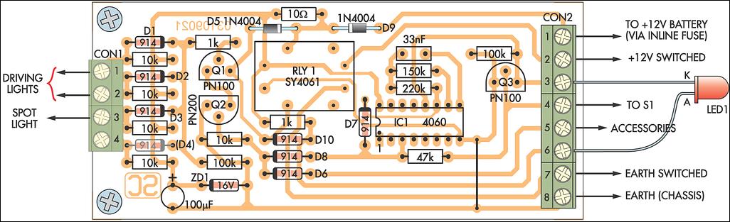
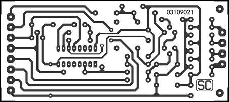
Begin by carefully checking your etched PC board against the published pattern (Fig.3). That done, install the wire link, followed by the resistors, zener diode ZD1 and diodes D1-D10. Make sure that the diodes are all correctly oriented.
Note that we have shown diode D4 dotted on both the circuit and the overlay. This diode should be left out unless you have a fourth driving light (or spot light) to connect to pin 4 of CON1. Similarly, diode D3 should be omitted if you don't have a spot light.
In most cases, there will only be two driving lights to protect, so only diodes D1 and D2 should be fitted. In short, only fit as many input diodes as you have lights to protect - ie, if you have two driving lights, fit only diodes D1-D2. If you have diodes connected to unused inputs, the circuit will false alarm.
The remaining parts can now be installed on the PC board. These include the 33nF and 100μF capacitors, transistors Q1-Q3, the screw terminal connectors, IC1 and the relay. Make sure that IC1 is installed with pin 1 adjacent to D7 and note that transistor Q2 in a PN200 PNP type.
Testing
Testing is best carried out on the workbench. First, link the active input terminals on CON1 together (ie, those with diodes) and run a wire to pin 8 of CON2. That done, connect the tamper LED (LED1) as shown in Fig.2, then connect a 12V power supply to CON2 (positive to pin 1, negative to pin 8).
Initially, nothing should happen and the current drawn should be only a couple of milliamps. Now cut the wire between the input terminals to ground, to simulate an attempted theft. You should immediately hear the relay click in and then, after about 90 seconds, it should drop out and the LED should illuminate.
Of course, if you had connected a siren between pins 2 and 8 of CON2, it would have sounded for 90 seconds. However, it's unlikely you would wish to experience this pleasure!
Troubleshooting
The most likely reason for it not to work is that LED1 has been installed backwards. Other likely possibilities include poor or missed solder joints, solder bridges (especially between the IC pins) and parts installed with incorrect polarity.
Having a diode connected to an unused input on CON1 will also cause problems.
Installation
Once the circuit is working correctly, it can be installed in the vehicle. And that's easier said than done because, depending on where the driving light relay is mounted, you may have to run some leads through the firewall.
Generally, the best place to mount the unit will be close to the fusebox/relay box. This will enable you to easily pick up power and run the input leads to the driving light relay contacts.
We'll leave it up to you as to how the board is protected. Typically, it could be wrapped in foam rubber and secured with cable ties. Alternatively, the board will fit inside a standard 130 x 70 x 40 plastic case, which is available from most suppliers. The tamper LED and Reset switch should be mounted in an accessible location on the dashboard and connected to CON2 via flying leads.
Pin 1 of CON2 must connect to an unswitched battery positive terminal. An unused position on the fusebox is a good place to pick up this connection but be sure to fit a 1A in-line fuse. In most cases, it will be just a matter of buying a fuse to suit your car's fusebox. Note that all connections should be run using automotive cable and connectors.
The car radio supply line is a good place to pick up the accessories feed. Again, this can be picked up at the fusebox.
Driving light connections

If the driving-light relay has double-pole contacts (ie, one set of contacts for each driving light), the leads from CON1 can be wired directly to the relay. Just be sure to connect each input to the driving light side of its contact.
However, if the driving light relay only has a single pole, you cannot wire CON1 to the relay contacts. That's because cutting the leads to one light would still leave a circuit back through the commoned relay contact and the remaining light - and that's just what we don't want.
There is a way around this however, and that's to run the leads from CON1 directly to the driving lights themselves. In fact, you have to make the connection to each light inside the lamp housing itself (so that the thief has to cut the wire). It really doesn't matter which side of the lamp filament you connect to - either side will do.
How can you tell whether or not the driving light relay is a single-pole or double-pole type? Simple, with the power off, disconnect one of the driving light leads from the relay, then check the resistance between its relay terminal and earth.
If the reading is open˜ircuit, the relay is a double-pole type. Conversely, if you get a reading of just a few ohms, it means that there is a path back through the other driving light and so the relay is a single-pole type.
Siren
In order for the unit to trigger an existing car alarm, you will need to connect one of the switched outputs to an appropriate alarm input terminal - ie, either connect the +12V Switched output to a high-going input trigger terminal, or the Earth Switched output to a low-going trigger terminal.
For example, if you car's alarm is triggered when a door opens and the courtesy light switch is in the ground circuit, then the Earth Switched output can be connected across this switch.
Alternatively, you can use a separate 12V DC siren. If you fit this behind the grille close to the items you are protecting, it should frighten daylight out of any thief.
Finally, note that this circuit will also sound as soon as you turn the engine off if the filament in one of the lamps "blows" - ie, it can also function as a "blown filament indicator". Of course, that's assuming that you have wired CON1 so that the lamp filaments are in˜ircuit. However, this feature will be disabled if you connect to the "earthy" side of the lamp filaments inside the lamp housing.
| Parts List
1 PC board, code 03109021, 109mm x 48mm Semiconductors Capacitors Resistors (0.25W, 1%) |
| Table 1: Resistor
Colour Codes
|
|
The following downloads are available for this article: |