| Having Space Constraint At Your QTH To Put Up An Antenna For HF Band?. Then Try Constructing This Magnetic Loop Antenna.(The antenna that is synonymous with 9M2SX in 9M2-land) |
Dwelling on the 7th floor of a 12-storey flats means that space constraint was the major problem for me.
Then the challenging task of using a suitable antenna for HF band arises when I got my amateur radio operating licence. Using a dipole antenna or beam antenna is out of the question because the building management does not allow me so. For those of you w ho are able to do so, consider yourself very lucky indeed.
I have tried using a dipole antenna and a windom antenna that was hooked up in such a way that the antenna wires did cover nearly the entire ceiling of my QTH which was also the floor of my neighbour above, hi. Lucky for me, my xyl is supportive toward s my hobby and could bear the madness in me trying to communicate with the world out there via amateur radio. My dipole antenna and windom antenna that was hooked up to the ceiling, looks like an incomplete gigantic spider web, and unfortunately it did not perform as it should like in the open space. Anyway, I did manage to have a few local contacts with very discouraging signal reports. So what else can I do?, back to the drawing board, hi.
Articles about the magnetic loop antenna have appeared from time to time in many amateur radio magazines, and now the latest means of obtaining information about it, is via the internet. With these relevent articles in hand, I experimented with many va riations of the magnetic loop antenna and never stop trying to improve the magnetic loop antenna’s performance since day one, hi..
The magnetic loop antenna is a small circular antenna that can operate on multi-band like 40m to 20m, 20m to 10m, and even tri-band, 40m to 15m. I was able to construct a tri-band magnetic loop antenna few years ago and worked many DX stations with it before the variable capacitor gave way for unknown reasons.
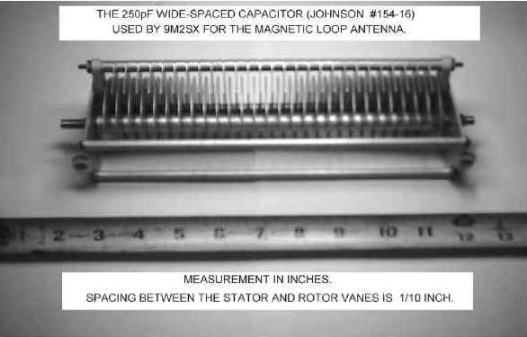
The bands that the antenna will be covering depend on the type of variable wide-spaced capacitor that you use. A split-stator type is recommended, but I have been using the normal type and it works just fine (see photograph). If you have the vacuum sealed type it is better.
I do not have an antenna analyzing equipment to work with. Just using my old trustworthy Oskerblock SWR-200 s.w.r. meter, a home made noise bridge and a passive field strength meter to do the testing. Not forgetting to mention much time and money was spent, trials and errors, own labour, etc. etc., that was put in my experiments with the magnetic loop antenna.
I started building my first on December 1988. First time on-air using the magnetic loop was on January 8, 1989 at 7.040MHz with 9M2DI, 9M2DW, 9M2SB and 9M2SH. Encouraging signal reports and comments was received. This paves the way for improving my m agnetic loop antenna. My first DX contact on 20m, using a improved version of the magnetic loop antenna, was with UC1AWZ on February 5, 1989. With good signal report received, I smiled ear to ear, hi..
The Construction
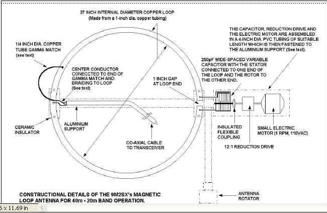
My prototype of the magnetic loop antenna was made from a 3/8-inch diameter copper tubing. It is best that you start first with a small diameter copper tube for the loop and then progress to a larger diameter later on. This will help you to understand more about the characteristic/performance of the magnetic loop antenna. About 11 feet in length of the copper tube was required to mak e a 37-inch diameter loop element.
The 3/8-inch diameter copper tubing (used for air-conditioning systems) is quite soft and I was able to bend it slowly by hand to the form a loop and trim of the extra length if necessary, taking into account the 1 inch gap at both ends of the loop (see illustration).
My later version is made from 1 inch diameter copper tubing. The antenna’s efficiency seems to be better with larger diameter copper tubing. I used the services of a local meta lworking workshop to bend the copper tubing into a loop. Th e whole loop was then mounted o nto a 1-inch by 1-inch square aluminium tubing support of suitable length. The aluminium support must be isolated from the loop by means of an insulator.
In my design, I used 2 pieces of 1/2 inch thick rectangular ceramic plate with ready made holes in it. Lucky me, I got this stuff from the junkyard, hi..
The insu lator must be placed between the loop and the support. Please take note that from my experiments and experience, using a metallic support for the loop ha ve very little effect on the overall performance of the antenna provided the support is well insulated from the loop. In my setup, the support is mounted on an antenna rotator. This setup allo w me to swing my antenna system in (when not in use) and out (when in use) of my QTH’s balcony, also to point towards certain direction or countries.
Please ignore the small loops t hat are placed inside the main loop (see photograph). Just refer to the constructional details if you wish to build one. My present antenna system is a mo dified version for added antenna gain and broadside direct ion of maximum radiation. It is a time consuming and extremely difficult process that if not done very precisely, can degrade the performance of the whole antenna system.
I will change my antenna’s configuration at will until I get the best results out of the magnetic loop antenna. As I have mentioned earlier, my experiments with this antenna has no ending yet, hi.. hi..

The Tuning Capacitor
This is the only critical component of the whole project. The magnetic loop is a tuned loop and is a very high Q circuit. High RF voltages appears across the capacitor vanes. An excess of 1000 volts may appear between the plates with an output power of 100 watts RF. That is why a wide-space capacitor is required.
The type of variable capacitor that is available in t he old broadcast receivers will flash over with about 25 watts output of RF power. Unless you decided to go QRP. then you can use this type.
The capacitor that I am using was salvaged from an old Collins HF linear amplifier hidden away in a corner at the junkyard. The wide-spaced capa citor has a ma ximum value of 25 0pF and 5kvdc working voltage (see photograph). This is ideal for 40m to 20m operations including 30m. The stator of the capacitor is connected/soldered to one end of the loop, while the rotor is conne cted/soldered to the oth er end using heavy gauge wires (se e illustration). To vary the capacito r, that is to tune the a ntenna to the resonant ferquency, I connect it to a 1 rpm 110vac small electric motor via a 12:1 reduction drive.
With this setup, I can remotely t une the antenna from my shack. You can do without the remote tuning system if you wish, but then it will b e neccessary for you to ply to and from your shack to the antenna in order to manually tune your antenna. If you opted for this, then remember to use an insulating spindle/knob attached to the capacitor. The whole assembly comprising of the cap acitor, reduction drive and electric motor is placed in a 4-inch diameter PVC tube housing using suitable bolts and nuts.
Both ends of the tubing is sealed as to make it weatherproof. Only the wires connecting the capacitor to the loop and power supply wires to the motor protrude out of the housing. The pvc housing assembly is then fastened to the aluminium support and make sure that the capacitor is not in contact with the support. The reduction drive and the motor is isolated from the capac itor by mean s of an insulating flexible coupling (junkyard stuff again, hi.. hi..).
The Gamma Match For Antenna Feeding/Matching System
Here I prefer the gamma match system over the small inductive coupling loop system as it is much easier to build and less critical to setup. Using a 22 inches long, 1/4-inch diameter copper tubing, I bent it to form a semi-circle. One end of the gamma match is connected to the center conductor of the RG-58 co-ax cable.
Please make sure that this portion is not in contact with the loop and weatherproof it. The other end of the gamma match is temporarily conn ected/soldered to abou t 10 inche s away from the mid-point of the circumference of the loop from the open end. The braiding of the co-ax cable is connected/soldered to the mid-point of the loop (see illustrat ion). Please bear in mind that you n eed sufficient length of co-axial cable from the intended location of your antenna to your transceiver before connecting your feeder cable. I used a 100w electric solder ing iron for the required job and good clean soldering contact is a must t o avoid RF losses to the antenna setup.
Tuning and operation
With all connections properly done and ante nna placed many feet away from you or others, switch on your transceiver in receive mode, the range of bands covered by your loop antenna. Select a desired frequency, e.g. 7.040Mhz, listen for band noise/signal. Now rotate/adjust slowly the capacitor until there a sharp rise in the noise/signal. Tune for maximum. At this point, it is said that the antenna is at resonance.
With a SWR meter in circuit, apply a very small RF power to the antenna, about 5-10 watts, and note down the swr reading. Select another frequency, e.g. 14.200Mhz, and repeat the procedure as for 7.040Mhz. You will have two different sets of swr readings for the two frequencies.
Switch off your rig and disconnect the co-ax at your rig. T his is for safety mea sure because soldering/unsoldering work done at the antenna end while using an electrical soldering can damage your rig if there is electrical power leakage. So don’t take chances!. Unsolder the end of the gamma match that was temporarily soldered to the loop earlier. Bend the gamma match slightly as required and resolder at about ¼ inch up or down from the original spot.
Proceed with the tuning procedure as before and noting down the swr readings. Repeat as neccessary until you get a minimum swr reading for both bands or fr equencies. Adjustment is very critical because of the antenna’s high “Q” and narrow bandwidth. After all is done and you are confident about it, then you can transmit with more power if you desire. Do not use an A.T.U. with this antenna. Please remember that the direction of maximum radiation from a magnetic loop antenna is in the plane of the loop antenna and not the broadside of the antenna.
Results From Using This Antenna
Please take note that I was unable to refer to any other fellow amateur radio operators in 9M2-land with matters pertaining to the construction and use of this antenna because at that time no other amateur radio operators was using this type of antenna way back in the late eighties and the internet was unheard of those days. I was on my own.
Good signal reports and favourable comments was received while having QSOs with local and DX stations. My favourite band for DX operation is 20m and sometimes I shall be having a pile-up, hi..
Here are some of many confirmed DX contacts mostly in SSB mode with my magnetic loop antenna.
On 40m with;
IK4TVK (Italy), HA0NAR (Hungary), ZS6YA (S. Africa).
On 20m with;
8J1RL (Antartica), VQ9RT (Diego Garcia), LX2EA (Luxembourg), JT1CC (Mongolia), VO1FB (New Foundland, Canada), S09NEL (Western Sahara), XZ1DB (Myanmar), XX9AJ (Macau), 9H3DN (Malta), EA8AM (Canary Is.), 9N1HA (Nepal), 5N7ET (Nigeria), EI2GS (Ireland), 9X5HG (Rwanda), GI0UJG (Northern Ireland), 9A2OM (Croatia), SM0HCI (Sweden), OH8LQC (Finland), LA7JO (Norway), OZ1FSD (Denmark), PT7BZ (Brazil), OM9SIAD (Slovak International Air Display (SIAD)). M100G (celebrating 100 years of radio, England). On 15m with; EA9AO (Spain), 9A2OM (Croatia), F5DGM (France), OZ7YY (Denmark), HB9KOF (Switzerland), OH2JPR (Finland), DL2HX (Germany), OK2SK (Czech Republic).
My purpose in writing this article is to show that even a small size antenna like my home made magnetic loop antenna can perform well provided that you put in much effort into the project. Please take note that I construct and use this antenna out of necessity and I have no regrets about it, hi.. hi..
Caution : Build and use at your own risk. Radio frequency radiation can be harmful to human health if safety is ignored. Please maintain a safe distance, at least several yards away, when using this antenna.
Happy DXing
73 and all the best
de Saito 9M2SX
March 2004
Page 5