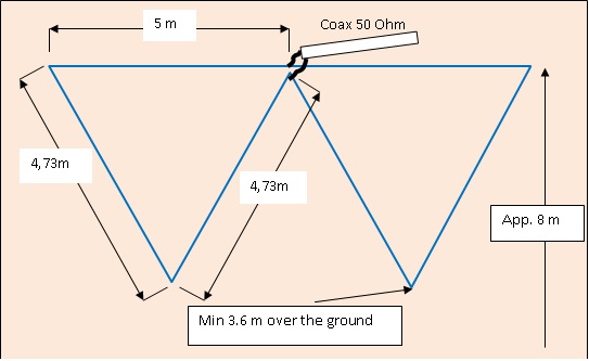
 On the left there is scheme of the antenna I built.
Given dimensions are the one after tuning to 21.050 MHz
On the left there is scheme of the antenna I built.
Given dimensions are the one after tuning to 21.050 MHz
For calculation of the length of the one loop I used the old formula:
300 / F MHz x 1.05 - results are in meters
You need two loops so the wire must be twice as long as the calculation is.
Keep the bottom part of the antenna at least a quarter wave above the ground!
 Here you see the way I attached the wire.
The horizontal part is made with a stronger wire since it must support the fishing rod to avoid too big a sag of it.
A wire is attached to the fishing rod with a strong tape of any type.
At the bottom apex, some 10 cm of wire is left for tuning the antenna to the frequency you wish.
My antenna was tuned to 21.050 ( SWR 1:1.15) since I preferred CW operations, but even though at the SSB end, SWR was 1:1.8.
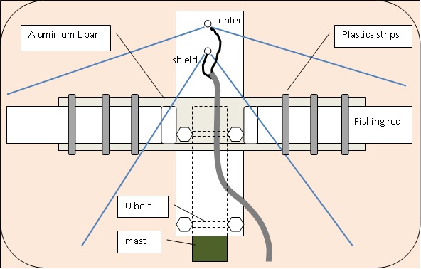 This sketch shows some construction details.
Keep in mind that this antenna was made for temporary use during the expedition only, think, some reinforcements should be done for permanent use.
To the insulator plate (8 x 40 cm) is attached an aluminum "L" shape bar 0.5m long. The fishing rod (make sure it is not made of carbon) is attached to the "L" shape bar with plastics strips. The center of the coax cable is connected to the horizontal wire and the shield to the bottom wire.
I prefer feeding my antennas with the half-wave long coax or its multiplicity. The half-wave-long coax does not transform impedance so the radio sees the same impedance which is present at the feeding point of the antenna.
You may determine the length of your coax cable (it works for monoband antenna only) according to formula:
[(300/F) x n]/2 where: F - frequency in Megahertz, "n" means any number so that the coax reach your radio
For the physical length of the cable, we must multiply this result by the coax velocity factor VF eg. 0.66 for RG58.
 Here is a photo of the center of the DL special DX just before going to the top of the mast.