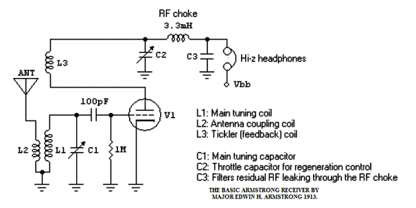
5Z4FT ARMSTRONG FET REGENERATIVE DETECTOR

Description.
In 1913 Major Edwin H. Armstrong patented a design for the Regenarative Receiver that uses the principle of positive feed-back in amplifiers to
demodulate AM, CW, SSB, and FM.
Mr. Armstrongs circuit is shown above and used the new three vacuum tube of the time.
The Regenerative receiver has since become the most popular basic receiver for Amateur Radio Operators and Electronics experimenters worldwide.
The principle of operation is simple. Positive RF feedback is used to increase the RF gain of the amplifier upto and beyond self-oscillation.
With no input RF signal the internal noise peaks and a small bias volatge combine to produce a stable but self-limiting oscillator,
except right at the peak of oscillation very high gain is produced and the detector becomes very sensitive to small input RF signals,
like those associated with SSB and CW. AM is demodulated just below the point of oscillation,
but SSB and CW are demodulated when an RF signal combines with the heterodyne signal to produce an audible beat tone.
Today the basic Armstrong circuit remains the same except, the large tunning capacitors have been replaced with Varicaps/Varactors while
vacuum tube with both Biploar or Field Effect Transistors.
Todays modern devices in a well constructed circuit, improve stability and lower internal receiver noise, and can be very sensitive in the right system.
Several modern designs for the basic Armstrong "Regen" have appeared in publications and on the Internet but the principle
Mr. Armstrong discovered is the same. The advantages of a "Regen" are the beat note, absence of a weak signal threshold, high amplification, and
practical simplicity for a reasonable Radio Communications reception return. The Receiver though, is more prone to atmospheric disturbances,
capacitative effects, QRM, and QRN, but for casual use, can be enjoyable to use and is well
suited for the first time radio communications home-brewing enthusiast.
Developers may be interested to note, that any device that can act as an oscillator,
can be used to create a Regenerative Detector, from electron tubes, bipolar transistors, and FETS to IC(Integrated Circuit) inverting buffer amplifiers,
with varying degrees of advantages and disadvantages.
The study of these, are a rewarding start in the understanding of oscillators, and a simple begining to the art of short-wave listening.
Perhaps Mr. Edwin H. Armstrong may have not know this at the time.
Below is a common re-work of Armstrongs Regenerative detector as an infinite impedance detector using a FET.
This one in particular has no real advantage over other derivatives, except a toroid core is
used in place of an air wound core. Modern toroids have a Q(Inductor product quality factor)
greater than 100 and with sufficeint regeneration a practical high Q can be maintained.
As a rough guide the relevant formula is [Frequency(Hz)/Signal Bandwidth(Hz)] = [Q * Amplification].
For Example[(21.060 * 10^6)/800]= [150(Q) * Amplification], results in a required amplification of 175 times, which is well within the
capability of any FET Armstrong detector. As a rough guide though do not exceed an amplification of 1000 times,
the lower the amplification factor and the higher the Q the better the output product.
A high FET amplification factor produces noise in the audio domain, justifying a low FET amplifier factor, and high inductor Q.
Use of a Lower FET amplification factor can be compensated for by suitable front-end adjustable band-pass filtering with RF gain
and coupling applications, together with a low noise audio filter amplifier and low noise figure FET.
Since Q and amplification are interelated an ideal Receiver based on these principles would have to have exact ways of controling
positive feed-back regeneration, RF input gain, RF input coupling, and low noise filter amplification,
resulting in a rather adequate HF Communications Receiver with many knobs to play with,
like in the early radio communications days, ported to present day technology and more efficeint.
C9 is any practical value that does not
affect tuning and allows a varicap diode together with a suitable DC blocking/scaling capacitor
to be used in place of C1. R5 and D8 limit the FET AGC for maximum transconductance.
The arrangement of the coil winding phases results in the best configuration to allow
maximum positive feed-back(both negative feed-back and positive are present) while inverting
the regeneration signal back 180 degrees since the FET gate drain arrangement inverts the signal -180 degrees.
The regeneration capacitor acts to "TUNE" the regeneration link coil, where-by more
capacitance allows greater feed-back couplng while less capacitance less feed-back coupling,
hence the name throttle(choking capacitor) capacitor in some publications.
