Ku-band LNA/LNB optimisation for 10.4 GHz
March 2019
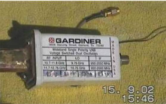
Example:
The visual detail
below shows how a Ku-band LNB was modified to improve
the front-end performance
for use at 10.368 GHz to monitor the ARRL's EME
contest in 1997.
After
the mod this LNB's front
end was vastly improved and the receiving
system sensitive enough to manually track the moon on
its moon-noise signature
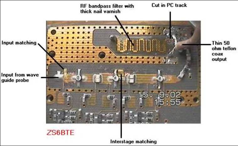
which was up to 2.5 dB. Only the input matching and interstage
matching is relevant to this discussion, but the
positioning will indicate
where we are going.
Moving the
front-end of a
Why bother?
Improving
the LNB's noise figure,
here the system noise figure NF or system temperature
T,
increases the noise power ratio (Pn=10
log(kTB)) and thus the
downlink signal-to-noise ratio in the case of a
satellite such as Es'Hail
2.
The
noise figure is defined
as NFsys dB
= 10log10
(Tsys /297
+ 1) where
the ambient temperature is typically about 297k, and
system T is composed of
the antenna noise as collected plus the temperature
contribution of the 1st and
2nd RF stages.
The
S+N/N on a satellite's
downlink boils down to: downlink EIRP - (-noise power
ratio of the receiver).
My standard unit under test had a noise power ratio of
10log(1.38
x10-23 x
2500 x 180) = -172 dB.
In
this
case the variables are fixed, only the system noise
temperature T can be
improved.
The
front
end can be improved to provide a system noise
temperature possibly around
42k by the look of it. The noise power ratio would then
be 10log(1.38 x10-23
x 2500Hz x
42k) = -178.3 dB. This is a 6 dB improvement in S+N/N which would otherwise have to be found by
enlarging the Rx dish
antenna's diameter 4x, i.e. a typical 0.8m to 3.2m.
Front end of an
Octagon OTLSO LNB
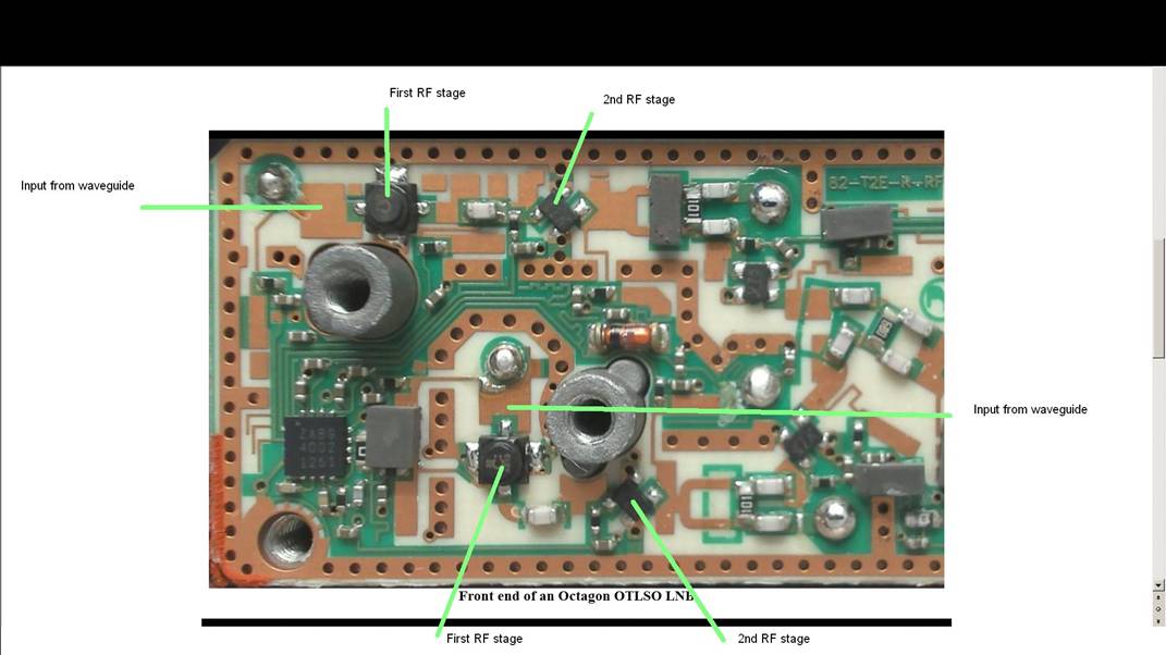
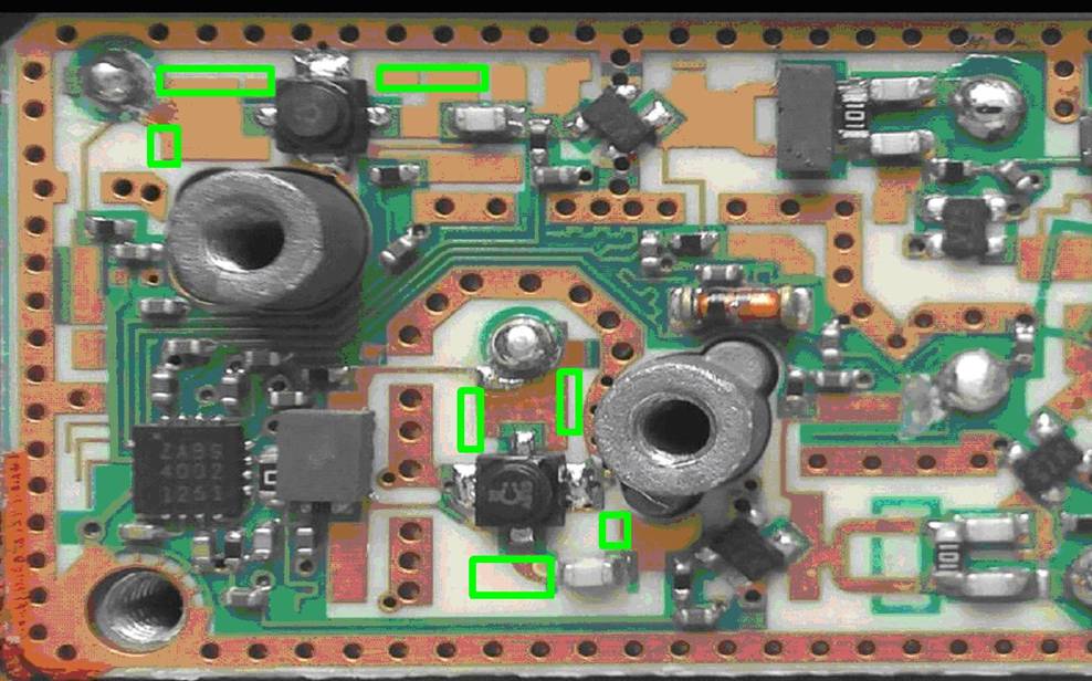
Possible zones to
install patch material
Information
This
popular LNB shows a
steep drop-off in performance between the bottom of the
satellite TV Ku-band at
10.950 GHz and the amateur X-band allocation around 10.4
GHz. These frequencies
are quite close.
Accordingly,
minimum patching
of the RF inputs will produce a substantial reduction in
noise figure.
Methodology
Required:
�
A device capable of
operating on the
IF frequency 740 MHz, in wideband AM mode, the wider the
better. Do not use
non-linear detection such FM. A
s-meter on a
suitable Rx is ideal, or the input of a dongle such as a
RTL
�
At least 20 dB
of IF
attenuation between the IF output
of the LNB and input to the Rx. Ideally the s-meter
should indicate about s-2
to s-4 when connected, the s-meter should not 'bottom'
at s-0 nor be hard
driven in excess of about s-5 or so. It should show some
'life' and move around on the random
noise peaks.
�
A handful of 1mm
squares of thin copper or brass shim. These squares are
temporarily fixed in
the green zones illustrated by wiping them in "stick'
such as Pritt so that they
do not fall off during the optimisation
process. They are then slid around using a pin or needle
between the readings
taken.
Optimisation process;
The LNB
may be mounted on the
dish antenna or waved around by hand. Apply 12v to the LNB's
input and note which RF input stage has a small negative
voltage on the gate
circuit attached to the waveguide input. This is the
front end handling
vertical polarisation, suitable for reception of the Es'Hail
2 satellite's narrowband transponder. The other first RF
stage will be off and
not have a bias voltage on the gate. Point the LNB's
input to a solid object nearby such as the ground or a wall,
this is the 'hot' body. Take the s-meter reading. Then point
to a portion of clear sky, the 'cold' body, take
the s-meter reading.
Note the reduction in received signal strength between
the 'hot' and 'cold'
body readings. Take several readings and average the
result. My standard LNB
yielded a RATIO
about 2.8 dB
assuming 6dB per s-unit (I actually used a 1 dB
precision stepped attenuator),
from this the noise figure was calculated to be 2.1 dB
and the system noise
temperature as 180k (see my test on this site).
Starting
with the input
(gate) of the active 1st stage, place a 1mm square shim
piece on the possible
zone illustrated above. Do not short to the nearby
ground plane of the PCB.
Repeat the hot/cold procedure. Take the average of
several results. Note
the RATIO,
this is important, more
than the actual peak readings. If worse move the patch
to a nearby position and
retest hot/cold. Add patches freely, noting the results
and positions.
Eventually the best result will be obtained using
patches on the input and
possibly the output of the 1st RF stage. There might be
some benefit doing the
same on the second stage to improve the conjugate match
between the 1st and 2nd
RF stages.
Up to
about 1 s-unit of
improvement (5-6 dB) should be quite easy, indicating
the LNB's
noise figure has improved from approximately 2.1 dB to
around 0.6 dB. I
reckon with a lot of care even more is
available as the LNB in native form might be good for a
NF around 0.45 to 0.5
dB at 12 GHz and the same at 10.4 GHz.
When
complete it is not
necessary to solder the patches, simply secure them in
position with a tiny
drop of superglue on the point of a pin.
Apply
18v to the IF line and
do the same on the horizontally polarised input. In
practise improving the
horizontal polarisation of this LNB is more important
because the wideband DATV
and RB-TV signals from Es'Hail
2 are marginal on
small dishes of around 80cm.