Oakdale ARC - CTCSS kit documentation & construction notes |
Oakdale ARC - CTCSS kit documentation & construction notes |
[ Home ]
These notes are for members of the Oakdale Amateur Radio Club who are intending to assemble the CTCSS board from a kit of parts. This page contains a number of pictures and graphics which means that it can take a little time to download on a dial-up connection. Wait for the page to load and then save the page to disk. You can then view it off-line.
This is the hardware schematic for the CTCSS generator:
This is an enlarged view of the PCB as seen from the component mounting side.
The silk screen on the upper surface of the board indicates the placement of the components. The pads and tracks are on the lower side of the board
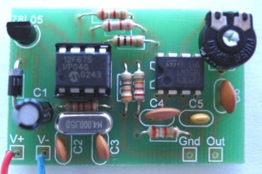
This is a view of a completed unit using the same components as supplied in the kit.
The actual size of the PCB is 47mm x 32mm (1.85" x 1.25")
Below is a bill of materials for the kit. I suggest that you print this and then lay out the components on the printed sheet next to the component number. If you are unsure of resistor colour codes then use an Ohm-meter to identify them. Be sure that you have all components correctly identified before you begin assembly. Note that C1 is the tallest component on the board. If reduced height is important, C1 could be replaced by a tantalum type capacitor. As an alternative, bend the leads of C1 at right angles and mount it in a horizontal position which will also minimize the height.
|
Component No |
Value |
Qty / Kit |
Marking |
|
|
PCB1 |
Printed circuit board |
1 |
||
|
C1 |
10uF Radial Electrolytic |
1 |
10uF 15V | |
|
C2, C3 |
27pF Ceramic |
2 |
27 | |
|
C4, C6 |
100nF |
2 |
104 M | |
|
C5 |
47nF |
1 |
473 | |
|
D1 |
1N4007 diode |
1 |
1N4007 | |
|
R1 |
2.2k |
1 |
Red Red Red | |
|
R2 |
3.9k |
1 |
Orange White Red | |
|
R3 |
1.8k |
1 |
Brown Grey Red | |
|
R4 |
1k |
1 |
Brown Black Red | |
|
R5 |
330 |
1 |
Orange Orange Brown | |
|
R6 |
22k |
1 |
Red Red Orange | |
|
R7 |
39k |
1 |
Orange White Orange | |
|
RV1 |
10k Preset pot |
1 |
10K 507M | |
|
U1 |
78L05 5V voltage regulator |
1 |
78L05 | |
|
U2 |
PIC12F675 - 04 Micro-controller |
1 |
12F675 | |
|
U3 |
LM358N dual op-amp |
1 |
LM358N | |
|
X1 |
4 MHz Crystal Low Profile |
1 |
M4.000J5D | |
|
SK1 |
8 Pin DIL socket |
1 |
Assembling the board
Before you begin make sure that you have:
If you are are wanting in any of these departments then you will do better to obtain a ready assembled board or get a friend to do the job for you. The PCB does have a solder mask which helps to keep the solder in the right places but it can only help to a certain extent.
Start by placing the 7805 regulator. This is the most difficult component because the pad spacing is very small. In retrospect I should have used a larger spacing. Align the 7805 so that the flat surface matches that on the silk screen. Carefully solder the middle lead first and then solder the 2 outer leads. Use your Ohm-meter to make sure there is no short-circuit between any of the leads. Next mount the 1N4007 diode with the white band (cathode) toward the 7805. Add C1 with the negative leg closest to the diode and the positive leg to the square pad.
Next insert the 8 pin DIL socket over the silk screen 12F675 position ensuring that the notch in the socket matches that on the silk-screen and solder the 8 pins. Insert the LM358 with the dot (pin 1) next to C4 on the silk-screen (see the prototype picture above) and solder it in place. Add the preset-pot RV1 and solder. This is the last of the components (apart from the PIC) which need to be aligned properly. All other components can be mounted either way around. Add the remaining components except for the PIC. I suggest you mount them in this order R1, X1 (a couple of mm above the surface to clear R1), C2, C3, R5, R6, R4,R3,R2, C4, C5, C6, R7.
The unit is now complete. You should only have 1 remaining component which is the PIC micro-controller. Before inserting this into the socket we need to check that the 7805 regulator is functioning correctly. Attach connecting wires to the V+ and V- pads. Feed somewhere between 8V and 30V to these leads from your power supply or battery via a resistor of around 1k. The resistor will limit the amount of current that the unit can draw should there be a short-circuit or other problem. Measure the voltage between pin 1 and pin 8 of the 8 pin socket. This should be 5V plus/minus 0.2V. If this is not the case then check carefully for solder bridges with a magnifying glass and correct the problem.
If all is well, remove the supply voltage and the series resistor. Insert the PIC with the dot (pin 1) closest to C1. Rotate RV1 fully clockwise and apply the supply voltage. If you have an oscilloscope you should see a 88.5Hz sine wave about 1200mV Peak to Peak at the 'Out' pad. As an alternative use an AC voltmeter to measure the output which should be about 0.5V RMS. You could also feed the output into an audio amplifier to check for correct operation.
Connecting the CTCSS unit to your transmitter.
This varies with each individual rig. Please don't ask me how to connect it to your rig because I simply don't know (unless it happens to be a FT225RD like mine).
In principle there are 2 steps to connecting the unit.
First you need a source of power to switch on the unit when it is required. This should preferably be a voltage between 8V and 30V which is only active on transmit. Even better is a voltage which is only active on split frequency (repeater) transmit. Finding such a voltage is a matter of studying the schematic or consulting a Guru. Only a couple of mA is required from the power source.
The second step is connecting the 88.5Hz output signal to the rig. This is done by connecting the "Out" terminal to a point in the TX audio (mic amp) chain. It is very important that this connection be made with screened cable. The best point varies from rig to rig so you will need to experiment. The output pad of the unit is a relatively low impedance so you will probably need to feed the signal to the audio chain via a resistor to avoid loading the TX audio chain excessively. As a rule of thumb, set RV1 (output amplitude) to mid point and select a series resistor that applies an approximately correct level to the transmitter. Use the lowest level which will access the repeater. RV1 can then be used to fine adjust the level. Do some experimenting, it is what the hobby is all about.
The PIC's are pre-programmed and have been individually tested. The prototype was accurate to within 0.01 Hz and gave a clean sine wave output up to 1200mV. Happy Homebrewing !