I recently purchased a Kenwood TS680S and noticed on reading the manual that it has an accessory port that is ideal for interfacing with a computer soundcard. The ACC 2 port has a DATA OUT audio line which is independent of the volume control setting and the PKS line switches the transceiver to transmit whilst disabling the front-panel microphone so only audio received through the PKD line will be transmitted. This is ideal for digital modes since it prevents "hot mike" problems when the microphone transmits ambient sounds during digital transmissions, which is poor operating practice and a potential cause of embarrassment.
This, combined with a growing interest in PSK31 (a digital mode which is designed for conversational QSOs rather than data transfer), led me to design and construct a soundcard interface for my new rig. Since I am a CW enthusiast I also included a separate CW keying line in the interface. While I do not intend to abandon my paddle for computer generated Morse for everyday use, this will allow me to use a logging program with integrated computer keying for contests.
Although developed for the TS680S, the same circuit should work for other solid-state transceivers - you will just have to use a different connector to access your rig's line in, line out and push-to-talk. If you don't have a line out then you should be able to use your external speaker jack or headphone socket, although then you will have to adjust the rig's volume control to get a suitable signal level for the sound card. Similarly if you do not have a line in with transmit/receive switching then you could make up a standard microphone plug wired for your rig and use this instead.
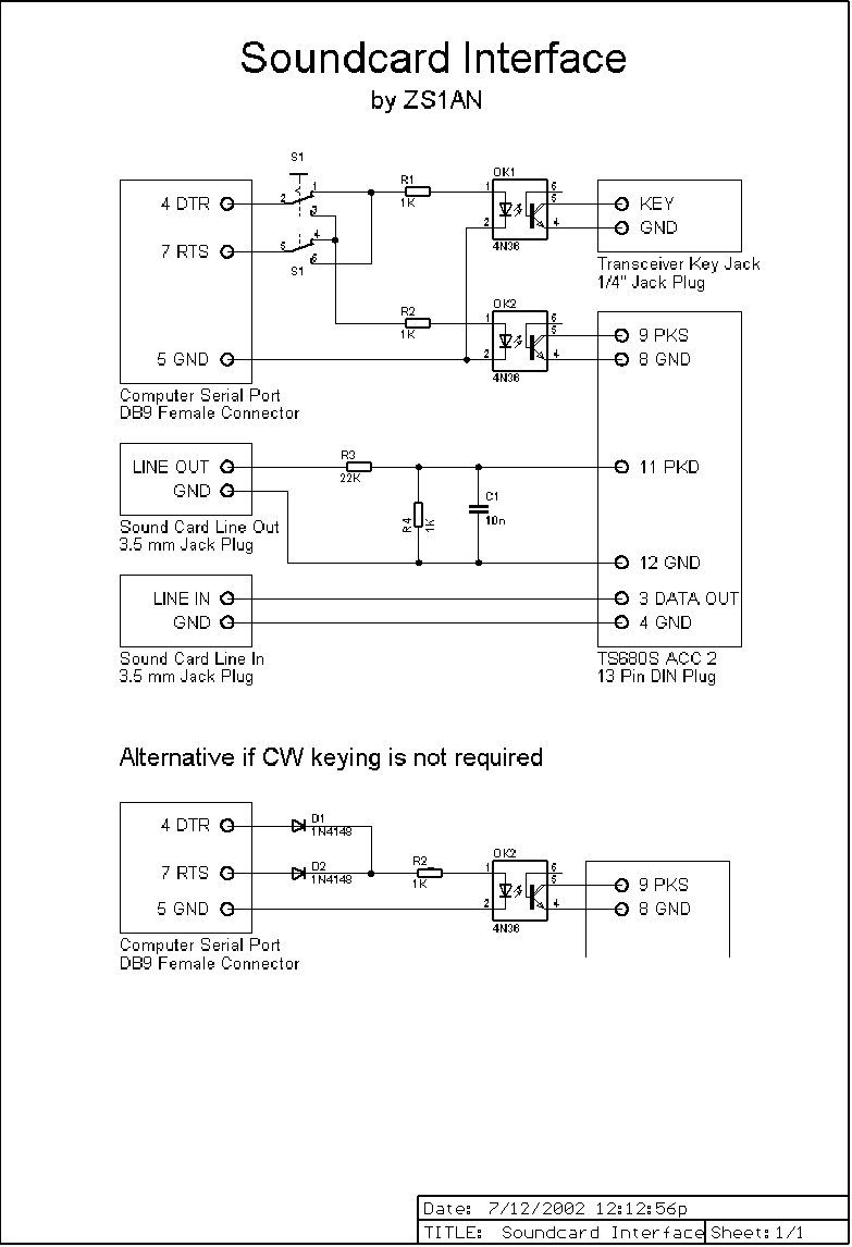
Click here for a bitmap image of the schematic (112 KB).
The computer's serial port is used to operate the keying line and transmit/receive switching using the DTR and RTS control signals. Since there is no standard as to which serial port signal should correspond to which transceiver function, toggle switch S1 allows the user to select whether DTR operates the keying line and RTS the transmit/receive switching or vice-versa. The signals are routed through current-limiting resistors R1 and R2 to opto-isolators OK1 and OK2, which isolate the transceiver interface from the serial port and perform the actual switching. I used 4N36 opto-isolators since they were easily available, but just about any general purpose opto-isolator should work. Note that the circuit assumes that the "KEY" and "PKS" lines are positive with respect to ground, and that the voltages being switched are in the 5-15 V region.
If you do not require CW keying then you may omit S1, R1 and OK1, and connect both DTR and RTS to R2 through small-signal diodes as shown in the inset. The diodes act as a logical "or" so that the transmit/receive line PKS will be switched when either DTR or RTS is enabled.
The "line out" (or "headphone") jack of the sound card is connected to the microphone input line of the accessory port (PKD). Since this requires a signal in the region of 10 mV, a voltage divider consisting of R3 and R4 is used to reduce the signal level. C1 decouples any RF that may have found its way onto the line. The "data out" signal is already at line level (approx. 400 mV) so it is fed directly to the "line in" jack of the soundcard.
Note that the ACC 2 connector of the TS680S provides separate ground pins for each of these signals.
The interface was constructed on a small piece of strip-board (board with copper tracks running in one direction and drilled on a 0.1" matrix, also known as "Veroboard"). The board was mounted in a small die cast aluminium enclosure, which was earthed to pin 12 of the ACC 2 connector for RF shielding. To minimize the size I did not use sockets to connect the leads to the interface, but rather soldered the leads directly to the board and led them out through appropriately sized grommets, with cable ties tight around the cables on the inside of the enclosure for strain relief. All cables must be shielded to avoid problems with RF pickup.
Operation is simple. Plug the cables into the correct sockets on the PC and transceiver, and fire up your favourite digital modes software. I use HamScope, an excellent public domain program by Glen Hansen KD5HIO that can be downloaded free from www.qsl.net/hamscope. It supports PSK31 (both the original BPSK and the newer QPSK), CW, MFSK16, RTTY and Packet and has an excellent spectrum scope display for tuning signals accurately. You should configure your program so that either DTR or RTS is used for transmit/receive switching, and the other of these lines is used for CW keying if appropriate.
If you are using a Microsoft Windows platform then start the Windows Volume Control by selecting "Start|Programs|Accessories|Entertainment|Volume Control" on Windows 98 and 2000 or "Start|Programs|Accessories|Multimedia|Volume Control" on Windows NT. Ensure that the "Volume Control" and "Wave" sliders are set midway and that neither is muted. Then select the Options|Properties menu item to bring up the Properties page, select the "Recording" radio button and click on "OK" to bring up the Recording Control. Ensure that the "Line" volume slider is set midway and that the "Line" input is selected.
Set the transceiver to USB, select your dummy load and try transmitting in PSK31 or your favourite digital mode. If you hear a CW side-tone instead, then change the position of switch S1. Adjust the Windows Volume Control and/or the microphone level control to get the audio signal within the ALC range, and have another amateur check the quality of your signal. This is particularly important since properly transmitted PSK31 has a bandwidth of under 100 Hz but overdriving the microphone input will generate intermodulation products over the entire 3 KHz SSB transmission bandwidth. On reception, use the "Line" volume slider on the Recording Control to adjust the incoming signal level.
PSK31 signals can be found near 14070, 21070 and 28120 KHz. The are recognizable as a carrier with a slight but distinct warble - much less harsh sounding than the FSK signals used by RTTY. Good hunting and I hope to QSO in a digital mode soon!