50Mhz HIGH GAIN ANTENNA AND MASTHEAD PREAMPLIFIER
BY MIKE BOSCH ZS2FM
*** First published in Radio ZS, April/May 1985 ***
An efficient antenna system is a prerequisite for more successful six metre operation. Most amateurs start off with a four element yagi, which is more than suitable for F2 propagation when signals are very strong. But when it comes to scatter and tropo work then results could be improved a great deal by increasing the antenna gain. Figure 1a below depicts a nine element long yagi on a 9.2m boom,which is effective over a range of 50.0 - 51.5 Mhz and if carefully constructed and tuned then the forward gain could exceed 12dB with reference to a dipole. Figure 1b shows the details of the gamma match and the dotted lines indicate which part should be enclosed in a weatherproof plastic box. The latter could also house the masthead preamplifier described below, as well as the antenna relay RLI.
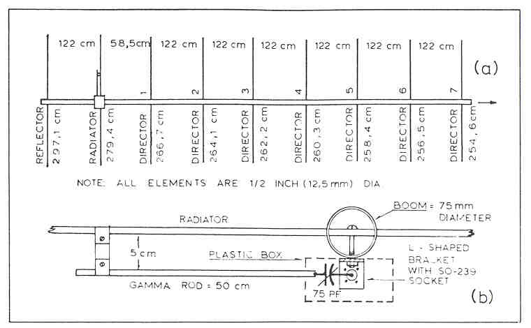
Figure 1: Long Yagi for 50Mhz
Another approach would be to stack two five over five or even
six over six yagis.
Municipal by-laws in many cities limit the maximum height of an amateur radio
mast to 40 feet (about 12.5m). A 50Mhz beam should be erected at this height
or even higher if legally possible, to produce low angle radiation and thus
improve both transmission and reception. For instance if a yagi is raised
from 8 to 12 metres then an improvement in performance of at least 3dB could
be realised. Another fringe benefit would be the elimination or reduction
of any possible RFI to your next door neighbour when operating on high power.
Many amateurs make use of the old medium-priced RG-8U type of coaxial cable to feed their six metre beams. Thinner cable such as the RG-58U should be avoided at all cost since its attenuation is considerable at VHF frequencies. Different makes of coaxial cable may have higher losses than indicated in the handbooks. A 100 foot (30.5m) length of RG-8U cable could register a loss of 2dB at 50Mhz. This attenuation in the coaxial cable would spoil the low noise figure of an efficient preamplifier. It is for this reason that the use of masthead preamplifiers should be encouraged.
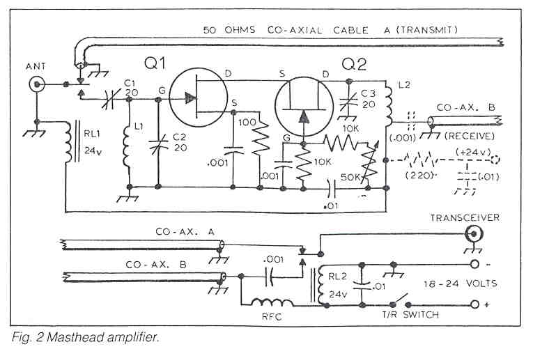
The preamplifier in Figure 2 uses a matched pair of ECG 452 FET's, and is
ideally suited for FM, since a great deal more front end amplification can
be tolerated on FM than on SSB.
If desired this preamplifier could be used inside the shack itself by omitting
the antenna relays and changing the output circuit as indicated in dotted
lines. Should the gain be too high for a particular type of receiver then
it could readily be reduced by shunting coil L2 with a low value resistance
of 2N,2K ohms or less. Alternatively a suitable attenuator could be fitted
at the bottom end of the receiving coaxial cable.
Coils L1 and L2 consist of 13 turns of No 20 gauge wire (preferably silver
plated) airwound on 7mm diameter. L2 is tapped at 4 turns from ground end.
The RF choke is wound with No 28 enamel wire over the full length of a 1m
2 watt resistor. C1 and C2 as well as the bias potentiometer must be adjusted
with the aid of a noise generator for minimum noise figure and consequent
maximum sensitivity for weak signal reception. Many amateurs have an erroneous
concept of noise figure as it should not be confused with the amount of noise
emanating from the loudspeaker when the volume is turned up.It is the ratio
of the noise generated in the first stage including its input circuit and
the reference which is level from a given weak noise source.
Mike Bosch ZS2FM
PO Box 1614
Port Elizabeth 6000
South Africa