CB TO 6 METRE TRANSVERTER
BY ANDRE BOTES ZS2ACP
It recently became evident, with the tremendous meteor scatter propagation on 50Mhz, how many people were interested in 6 metres but could not join in the fun because they had only FM transcievers or no 6m equipment at all.
This easy modification will allow the homebrewer to construct
an external transverter to be used in conjunction with an SSB CB set to which
no major modifications have to be done at all!
The mixer circuit described here is similar to that used for the 7Mhz conversion
(see RADIO ZS, October 1997 and April 1998) but with important differencesin
the tuned circuits and choice of crystal.The sum of the CB frequency plus
the mixer's crystal frequency will determine where in the 6m band you will
come out.
Note that this project is intended to drive a recycled commercial or other
VHF amplifier that you will need to acquire yourself. It should have a pre-driver
stage of its own since the output from this unit's pre-driver is very low
- only a couple of milliwatts.
Since a 40 Channel CB set will give you 400kHz coverage in the band, choose
a crystal that will place you in the segment of th 6m band where you wish
to operate. (As the DX section is in the low part of the band, ie 50.000 to
50.200, this will be the choice in the majority of cases)
Channel 1 on all CB sets is 26.965 Mhz and a crystal of 23.035 would be needed
for 50 Mhz exactly. This is an oddball frequency, so check for a 23.000 Mhz
crystal in the junk box as this will work nicely.
The oscillator used in this projectoperates at the fundamental frequency
of the crystal, and you should ensure that the correct frequency is generated
when you power it up! An overtone crystal may well be marked 23 Mhz
but it will actually oscillate at a fraction - a submultiple - of its marked
frequency in this circuit!
Populating the board is pretty straightforward. Ensure that you do not deviate
from the capacitor values as stated and keep all connections as short as possible.
The TX output power of the CB set must be turned to no more than 100mW otherwise
saturation of the mixer will result.
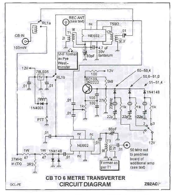
FIG 1: Circuit Diagram of Transverter
The gain of the pre-driver and linear amplifier added after the mixer board
will determine the final output on 6 Metres. I managed to scrounge the final
out of a commercial "no name brand" VHF radio, biased it for SSB
operation and am quite happy with the resulting 10 watts.
The linear amplifier that you select should also have its own antenna relay,
the "receive" contact of which should be connected to the terminal
marked REC ANT on the mixer board.
If you wish to use the mixer only for receiving 6 metre signals, you can connect
your antenna direct to this point, of course.
FIG 2: Overlay
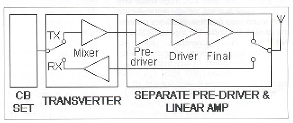
FIG 3: Block Diagram
FIG 4: PC Board
ALIGNMENT RECEIVER
Set the preset potentiometer to mid position. Select a channel on the
CB set to receive an appropriate 6 metre signal, the frequency of which will
be the sum of the oscillator and the CB frequency. A strong local station
or beacon would be ideal.
Adjust the input trimmer (the 80pF capacitor at T1) for strongest received
signal. The result should be very good.
Final tweaking of the CB's front end may improve the signal even further.
(I made provision for adding a low noise pre-amp to my unit at a later stage
but found this to be unnecessary)
ALIGNMENT TRANSMITTER
Connect a frequency counter to the output of the TX mixer marked "To
Separate Predriver". Switch the CB set to transmit in the AM mode. Adjust
the 80pF transmit trimmer near T3 so that the counter displays a frequency
in the 50Mhz range (depending on the crystal you have selected), thus ensuring
that the filter is suppressing the unwanted mixer frequencies.
To adjust the output to the exact frequency, each crystal should be selected
in turn and its associated trimmer tweaked for an appropriate reading on the
counter. If a 50Mhz receiver is available and a small length of wire is attached
to where the frequency counter was connected, you should be able to monitor
yourself on the receiver.
FIG 5: The Completed Transverter
INPUT And OUTPUT COILS
The 6mm formers seen in the photograph were removed from an old Pye Westminster
transciever, but almost any 5 to 7mm former would do as long as the pins line
up with the PC board. The coils are not fitted with slugs.
Should sufficient interest be shown, I will consider publishing options for
adding FM to the CB set and a complete linear amplifier, including a pre-driver,
that will be suitable for use with the mixer board described above.
Andre Botes ZS2ACP, [email protected]