Return to Index
Return to Projects
This project was designed to allow the remote control of relays at a repeater site (or anywhere else) via DTMF tones sent by radio.
Features:
8 individually addressable open collector outputs with inductive spike suppression, suitable for driving relay coils.
4 digit PIN number access restriction to relay control commands.
PIN number can be changed remotely with DTMF command.
Following a power interruption, all relays assume their previous state before the power interruption. (relay states and PIN are stored in non-volatile memory)
Relays can be remotely turned off, on, or pulsed from 1 to 10 times
Circuit description:
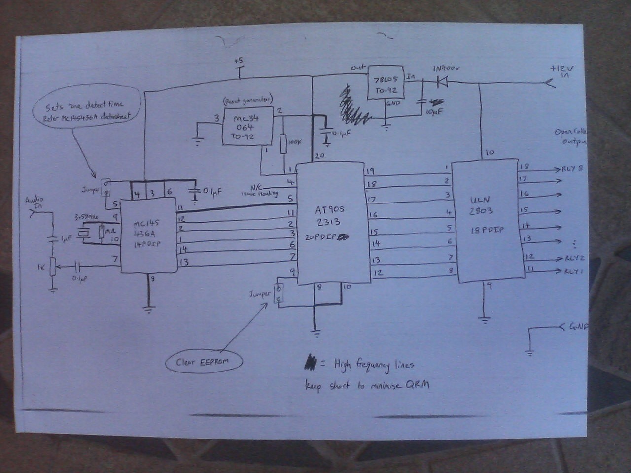
This circuit runs from the standard nominal 13.8 volts DC power supply. A 78L05 regulator is used to supply a regulated 5VDC logic supply.
An Motorola MC145436 DTMF decoder is used, this IC is clocked with a common 3.58Mhz NTSC colour burst crystal and supplies a divide by 8 clock output (about 450 Khz) which is used as the clock for the Atmel AT90S2313 microcontroller. As this MCU does not have a "brown out detector" feature, a MC34064 is used as a reset generator to prevent possible EEPROM corruption at abnormally low supply voltages.
Audio from the radio RX is fed to pin 7 of the DTMF decoder. When the DTMF decoder detects a valid DTMF tone, it outputs a nibble representing the tone on pins 1,2,13 & 14 and it drives pin 12, it's Data Valid output, high, which drives pin 11 on the mcu high. This wakes the mcu up from sleep mode, and the mcu samples the nibble on it's input pins 2, 3, 6 & 7.
Depending on the sequence of DTMF tone data supplied to the mcu, the mcu uses it's pins 12 - 19 as outputs to control the relays, these outputs are fed to a ULN2803 open collector driver IC, which drives the output lines.
Microcontroller pin 9 is used as a clear EEPROM input to reset the PIN number back to default and set all relays to off.
Remote commands:
All DTMF commands sequences start with a [*] and end with a [#]. Decoded DTMF tones are stored in a tone buffer, the command in this buffer is executed when the DTMF tone for the [#] key is received. Reception of the DTMF tone for the [*] key will clear the buffer without executing it.
[*] = clear buffer
[#] = execute command
Setting the PIN:
[*]+(old PIN)+[9]+(new PIN)+(new PIN)+[#]
The default four digit PIN is [0][0][0][0]. Every PIN must be four digits long, no more, no less.
The two copies of the new PIN must be identical, otherwise the PIN will not be changed.
For example, to change the PIN from [0][0][0][0] to [1][2][3][4], send the following command:
[*][0][0][0][0][9][1][2][3][4][1][2][3][4][#]
Remote relay control commands:
[*]+(four digit PIN)+(relay address)+(command)+[#]
or
[*]+(four digit PIN)+(relay address)+[3]+(number of pulses)+[#]
Valid relay addresses are from 1 to 8 inclusive.
Valid relay commands are [0] = off, [1] = on, and [3]+(x) = pulse relay x times.
Valid values for the number of pulses are 1 to 10, where 10 is represented by a [0] DTMF tone.
When a relay is pulsed, it will change state (XOR operation), wait about one second, then change back to it's original state and if more than one pulse is being generated, there will be an approximately one second delay between each pulse. During pulse output, the controller is deaf to incoming DTMF tones and you must wait for the end of the pulse sequence (maximum of about 20 seconds for a 10 pulse command) before sending another command.
For example, to turn relay #6 on:
[*][1][2][3][4][6][1][#]
To turn relay #6 off:
[*][1][2][3][4][6][0][#]
To turn relay #2 on:
[*][1][2][3][4][2][1][#]
To pulse relay #6 4 times:
[*][1][2][3][4][6][3][4][#]
Reset PIN to default:
After loading the firmware into a new mcu, the PIN must be reset to default.
Disconnect the DTMF relay controller from it's power supply.
Disconnect any devices from the controller output that you do not want to be activated by relay operation during reseting of the controler.
Use a jumper to pull pin 9 of the mcu down to GND.
Reconnect power to the DTMF relay controller.
Wait about one second.
Remove the jumper from mcu pin 9 so that the internal mcu pullup can pull it high.
Wait about one second.
Disconnect the DTMF relay controller from it's power supply.
The PIN is now reset to default and all relays have been set to off.
Issues and to do?
PIN is sent over the air as plaintext and this is vulnerable to interception. Also is vulnerable to a simple replay attack with a recording/playback device. A rolling code type authentication system might be the answer to this but then the commands will be more complicated - probably too complicated to keep in your head.
An ATmega8 or similar has a brown-out detector on die and could probably decode the DTMF tones in software (Goertzel algorithm, etc) - thus eliminating both the MC34064 reset generator and MC145436 DTMF decoder ICs.
Assembled firmware
AT90S2313 datasheet
Assembler source code
Assembler include file
Circuit schematic
Sorry, but no PCB or photos of the finished controller are available for this project.
MC145436 datasheet
MC34064 datasheet
ULN2803 datasheet
This page last updated 3rd October 2009