|
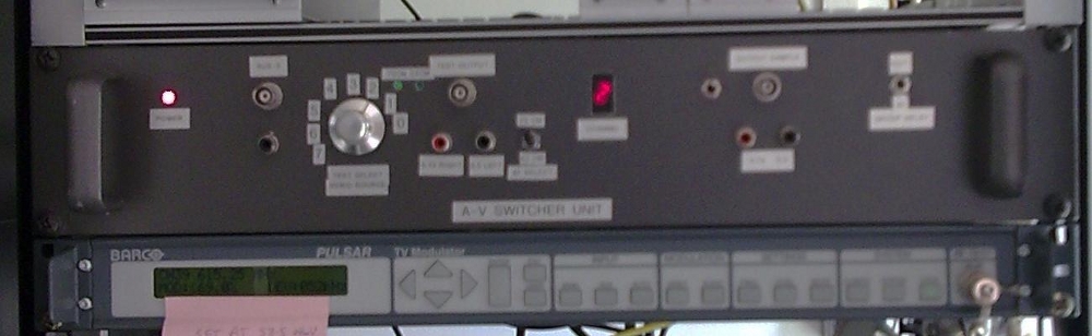
The current Auckland ATV repeater layout 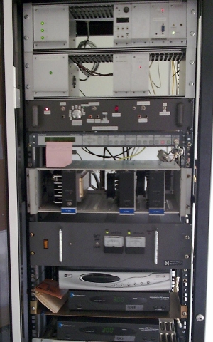
|
Power supply, Controller and 2m receiver units
Power supply, Teletext and colour bar units
8 way Audio video switcher
Channel 39 (615.25 MHz) Barco VSB modulator
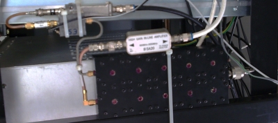
RF Power and driver amplifier stages
Power supply for RF amplifier stages
Digital receiver (DVB-S) 23cm input
FMTV analog receivers A and B 23cm inputs
|
The picture above shows the current repeater configuration. Most ATV repeaters have two modes of operations, one is Beacon and the other is Repeat mode. When the repeater is not in use, people will see information pages or colour bars being displayed. There are two inputs on the AV switcher that have sync detectors on them which detect an incoming video signal. The sync detectors work by a PLL locking to the video line sync frequency at 15.625 kHz. When this happens, a logic level is sent onto the controller, then the controller addresses the three parallel lines back to the switcher. This selects the appropriate AV signals to feed through to the modulator. The 8 way switcher also has a video overlay display function for status messages
|
|
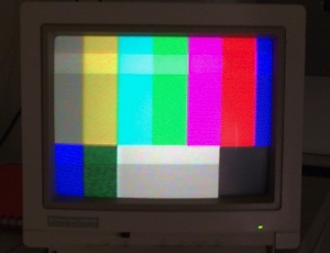
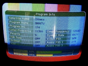
On the left is a screen shot of a received TV signal from Ken (ZL1TD) at the repeater site. Almost a P5 picture transmitted from Mount Roskill. The image on the right was received by Ken having been relayed out on channel 39 sent by Ralph (ZL1TBG) via digital TV.
Repeater layout
Audio Video 8 way switcher unit
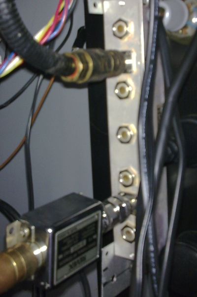
Filters
|
|
The 50cm Transmit filter is on the left and the 23cm Receive Filter is on the right. The transmit filter is designed to be 8 MHz wide to only pass channel 39 and to minimise any out of band noise. The receiver filter is present to prevent any overloading on the preamplifiers. Just above the 23cm band there is aeronautical radar to deal with and also below the band there is a small amount of second harmonic from the channel 39 transmitter at 1230MHz.
Digital repeater upgrade
We feel by doing this it would promote activity on the repeater as well as providing new possibilities. At the moment we are trying to work our way through expenses that come with this change over. I can see a number of opportunities with these upgrades. One is a MUX that let us have more than one TV channel on 39. A good number would be four channels in the MUX as demonstrated below.
With 8 MHz DVB-T there are a number of bit rates that can be used. This in itself opens up a whole new area of experimentation. As shown in the table below, there are 3 types of modulation, 4 different guard intervals, and 5 Coding Rates available to choose from to yield varying bit rates
The QPSK modes look very good for improved signal to noise performance, but it limits the data bit rates, whereas the 16QAM modes could be a good compromise for the ATV repeater.
By using a multiplex, we need to increase the number of input frequencies on the 23 cm band. I understand the need to keep at least one analogue FMTV input. It is important that current users and newcomers still have access to this repeater. But we also need to add a number of digital channels as well. This is why I have been looking around for filter for this band. This is the band plan that I have come with.
|
The 1283 MHz input analog and digital plus beacon mode, they will be the same on channel 1 as they are now The 1248 MHz analog input will go on channel 2 of the mux (NASA TV) The new 1264 MHz digital input will directly connect through to channel 3 And channel 4 in this mux will just display the teletext page |
As you can tell there is a lot possibilities left in ATV that are to be explored. So lets get the interest going in this new area of technology!
The home QTH ATV equipment
To access the ATV repeater you need a video source and a 23cm FMTV transmitter with a 6 and 6.5 MHz sound offset. There are two designs that can be built up - the ZL1WTT MK1 and MK2 ATV modulators. Transmit power requirements depend on your location in the Auckland. 2 watts is all that is needed for the West and Central areas with a good outlook to the Waitakere ranges. Out East and South, you could be looking at 10 watts. Suitable 23cm Amplifier power blocks are the M67715 and M57762, and there are now newer FET power blocks that are also available.
It is also important to use low loss coax for this band such as LMR400, LMR600 or LDF450 with N-type connectors. Aerials used for 23cm are normally Loop Yagis with 16 to 21 dBi of gain. These come as kits that you can assemble in your spare time. They are light and also have low wind loading and can be mounted on a normal roof mount such as a stayed TV mast.
Basic Television Repeaters
A 23 cm receive aerial is connected into a RX receive filter as seen below. After the filter, there is a low noise pre amp about 1.2 dB NF for 23 cm. Next there is a narrow band FMTV receiver, normally set for 15 MHz of bandwidth. The video output from the 23 cm RX goes into the sync detector.
The sync detector will switch over from the internal pattern generator when there is line sync present at a frequency of 15.625 kHz for PAL TV system. Then the repeater will switch from beacon mode to repeat mode.
The pattern generator that operates in the beacon mode generally displays repeater information. Typically a teletext generator is used for this application.
After the sync detector, the switched audio & video (AV) is feed to the vestigial side band (VSB) IF modulator. The IF output frequency is at 38.9 MHz. VSB TV signal is then mixed up to the RF frequency at 615.25 MHz or 50 cm band, then into the PA stage. UHF RF amplifiers must be keep in a linear mode of operation. i.e. class A or class AB only. There are four stages of amplification to get 5 watts average of RF output.
The second block diagram shows
A TV repeater is fitted with a microcontroller that is connected to a FM receiver, in this case 2m RX. With a remote receiver fitted, data can be sent up to the ATV repeater. Or you can use your 2m transceiver for remote TV sound or Ham radio nets. The Microcontroller controls functions in the TV repeater such as TX on/off, TX power adjust, teletext page changing, updating teletext page information, and RX switching etc.
In band TV repeater
Like most other Ham radio repeaters that have inputs and outputs in the same band, an ATV repeater can be constucted the same way. To achieve this you will need good input/output filtering as well as suitable receive and transmit aerial isolation. For example, the Whitford 23 cm TV repeater receives on 1284 MHz and transmits on 1248 MHz. The repeater split is 36 MHz and considering that the FMTV signal is 15 MHz wide, filtering needs to be designed for this type of application.

Sync detector for ATV repeaters
Bruce Churcher ZL1BLB
In the construction of an Amateur Television repeater station for the 50 cm band (channel 39 615.25 MHz), several methods of detecting the incoming 23 cm video signal were tried. This design using a transistor sync separator, 15.625 kHz tank circuit and NE567 PLL IC is the most effective so far. It responds only to video modulated signals. A 'tail' timing RC network between the IC and the relay driver transistors holds the relay in through momentary video glitches, such as switching from camera to videotape.
The double pole changeover contacts of the output relay switches audio and video to the transmitter from the beacon mode sources, (locally generated at the repeater) to the incoming audio and video from the receiver.
Setting up the detector involves adjusting the 4k7 preset adjustable resistor for the middle of the locking range, when a video signal is applied to the input of the circuit.
Several of these Sync detectors are now in use around New Zealand in ATV repeaters. The individual amateur can use one of these detectors in the path to his ATV transmitter to automatically switch a callsign generator on air when there is no other video signal applied e.g. when the videotape being played comes to an end or the camera is switched off.

Linear TV repeaters
This RF repeater works by receiving and transmitting on the same TV channel / frequency. To get this type of repeater to work geographical location is important. The receive section must be separated from the transmit side. If this type of repeater is on a hilltop, you would place the receive section on the opposite side of the ridge to the transmit side. Polarization is flipped 90 degrees between the input and the output sections. Changing the polarization will help with isolating both sides of the repeater.
This TV translator works by down converting the receive channel / frequency to IF frequencies, then mixing the IF signal back up to RF frequency again. Also could be used as a channel converter, as no demodulating is required.