
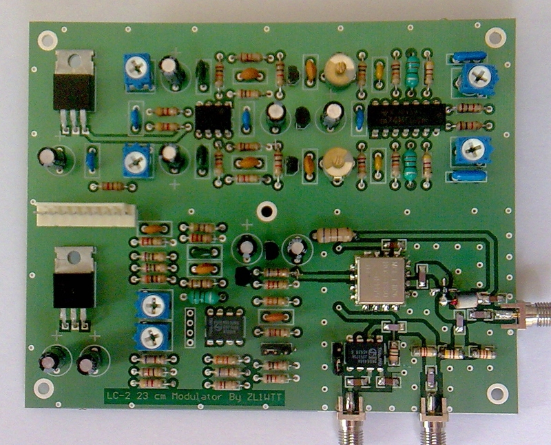
Low cost ATV modulator
ATV (Amateur Television) on 23cm:
This band is mainly used for repeaters inputs and simplex contacts. All ATV repeaters in New Zealand use FM modulation on their analog inputs. This is done because this provides improved signal to noise performance over the older AM.
The modulation bandwidth used on the Auckland ATV repeater is 18MHz this was best compromise for video quality and signal to noise. There for the receiver needs to be aligned for this bandwidth as well. It’s like trying to use a wide-band FM broadcast receiver to demodulate narrow-band FM voice, it will work but not very well. This is why it is important to set up the receiver to match the transmitter.
Back in the mid 1990's was when we started move away from AM on 70 cm and up 23 cm FM the Auckland ATV group decided to go with dual carrier system for sound. Where the 6 MHz channel became left and the 6.5 MHz was the right channel. The 6 MHz and 6.5 MHz sub-carriers came about for this reason, with most video senders coming widely available on the local market this became a common standard that was used. It is important when using inter-carrier sound to shift the these carriers to highest IF frequencies possible in my case this is 6 and 6.5 MHz. On the under standing if there is any inter-modulation it will start to happen from the fundamental frequency and start to move out from there. If the sound IF is to low this will start to noise up the picture at a lower level, if it is too higher frequency this will increase the over all band width of the transmitter.
Introduction:
ATV modulators are simple things to build, all you are basically doing is frequency modulating a VCO (Voltage-Controlled Oscillator), as you will see in this article.
This project is based around finding away of providing an ATV transmitter for those who would like to give ATV ago at the same time keeping the overall cost low. But it is also very important to come up with a modulator design that has low distortion as well. So I have come with this design that meets both of these requirements.
Features:
1/ Most of the components are leaded, to make assembly easer.
2/ Wide video bandwidth DC to 5.8 MHz
3/ The modulator is able to, do positive or negative modulation.
4/ Simple, to place on frequency, with the aid of the on the built-in prescaler chip:
for the 23 cm band
5/ Frequency agile oscillator
6/ Dual sound sub-carriers set at 6 and 6.5 MHz.
7/ Able to be connected to an external PLL and PA stages.
8/ Works over three bands 23, 13 and 9 cm
Circuit Description:
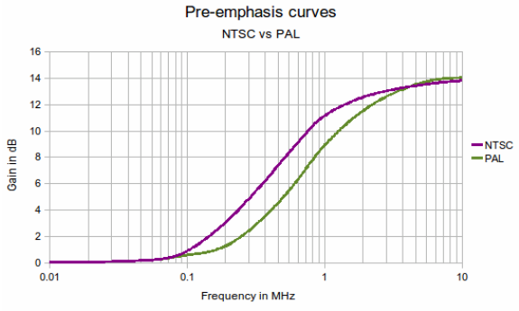
The incoming video signal goes via a PAL pre-emphasis network which is DC coupled to pin 1 of IC3 (NE592-N8). Pin 1 is biased to approximately half supply rail voltage by means of the two 680 ohm resistors connected to it. The sound sub-carriers of 6 MHz with an additional second carrier of 6.5 MHz is AC coupled in, after the pre-emphasis network to pin 1 of IC3. The second input, pin 8 is the tuning supply rail that adjusts the VCO bias voltage. VR6 alters the amount of signal gain / deviation of the FM signal by changing the amount of internal feedback inside the NE592-N8. Pins 4 and 5 of IC3 are the positive and negative going outputs, one of which is connected via JP1 to the BC559 transistor Q1. There is also an external negative feedback resistor added R29 to provide improved linearity.
For NTSC users:
You will need to change these components in the pre-emphasis network;
R20 (300) to 270 ohm
L3 (10uH) to 18uH
C22 (680pF) to 2.2nF Green-cap Polyester
VR5 sets the bias via IC3 from 0.5 to 5 volts on the output of Q1, this set the turning range of the MAX2754 IC4. The bias voltage on the input to pin 8 of IC3 should in the range of 2.5 to 6 volts. The oscillator consisting of a VCO IC4 in a SMD uSOT package, this has simplified the oscillator design.
IC6 (SAB6456) is a divide by 256 or 64 pre-scalar IC that can be used for a test output, ie for a Frequency counter or Oscilloscope to measure the output frequency. This output should read between 4.7MHz and 5.3MHz when set to divide by 256. JP2 sets the divide by ratio, closed for 256 and open for 64. This IC can be left out if not required.
IC5 (ERA-5) pre-driver MMIC amplifier after the VCO stage. That drives two RF outputs one has an 8dB pi-pad this is the PLL pick off point. Making sure that there is a degree of isolation between RF outputs. From the 9 Volt supply R38 is the dropper resistor half watt feeds the choke to supply power to the ERA-5.
The dual sound sub-carrier circuit uses two IC's IC1 (TL072) and IC2 (74HC04), plus two ceramic filters at 6 MHz and 6.5 MHz. The TL072 op-amp has the 50uS pre-emphasis and provides the gain. The 74HC04 hex inverter, has two inverters that make up the oscillator and the third one is the buffer stage. the ceramic filters are feed via 560 ohm resistor cleans up the waveform. This simple circuit works well and provides more then enough drive for the video stage.
IC’s 11, 12, 13 and 14 are the on board regulators (78L05, 7809, 78L05 and 7809) provides all the needed voltages. IC13 supply 5 volts to the pre-scaler IC and the VCO IC4. IC14 supples the NE592-N8 and the BC559 transistor. IC11 and 12 supply the sound IF stages.
Notes, C23 is a Green-cap Polyester, all trimpots are sealed mini standard size. Do not use open carbon trimpots on this project!
Prototyping:
One thing that is very important to remember is time that goes into designing a project like this. So far from the initial idea to a working prototype this has taken about 120 hours of my time. But the end product is worth it, it will prove very good service and it will get more operators on the air and enjoying ATV.
Problems that I run into on this project:
Cost was always a problem, I needed to cut back this design where possible keeping the components count to minimum. There for there is a few areas in this circuit where these compromised are made. This is why I went with this cut down sound IF layout, it’s a simple design.
Linearity is the next big problem in the way of video distortion. With this design I have managed to keep the total harmonic distortion down below 5% where by most of this is in the VCO. Many FM TV modulators that I have tested are some what poor in this regard. I found by comparing two VCO one was a Mini-circuits POS-2000 and the other a Maxim MAX2754. The overrule performance was far better with the POS-2000, but this VCO did not go down into the 23cm band. So I needed to make best of the MAX2754 and its non-linear response. This VCO requires a gain adjustment up to 4dBs at the top end of the band. So I will need to use the PWM function from the Micro-controller on the PLL board as an offset for the gain control. The sound sub-carriers levels were running at -18dBs down on the on video level with no noticeable inter-modulation. With the POS-2000 I could run these sub-carriers at -14dB with. same amount of inter-modulation. With improvements over time and more suitable VCO (ROS-1330) I could get my sound IF levels up to 20% of the video input level, with minimal amount of inter-modulation.
Below there are the two voltage tuning grafts showing both types of VCO tested.
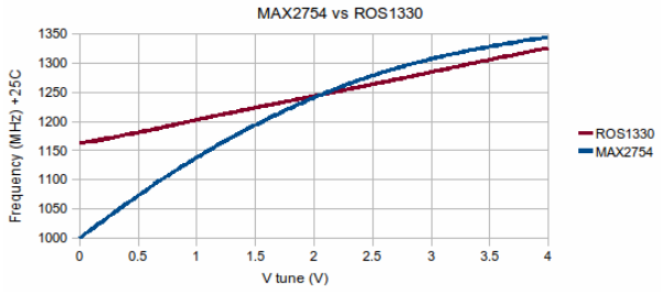
VCO Tuning curves
This is why I moved away from the MAX2754 based VCO and now using the LC-2 modulators with ROS Surface mount devices. By doing this I now can operate this modulator on three bands with far better linearity.
Bands:
23 cm 1200 to 1330 MHz, 13 cm 2250 to 2550 MHz, 9 cm 3280 to 3550 MHz. So it
It is as simple as a change of VCO for any one of these three bands.
Debugging this circuit:
I did this by using a test de-modulator and went through each stage of this circuit. On the sound side I had a TDA9821 PLL dual FM receiver that could test the sub-carriers at their IF frequencies. This is how I work out a number of the components values. On the video side I made up test de-modulator on a bit of vero-board and went through the stages in the same way. I found that I only needed to change a relative small number of components values. I also discovered that there was a requirement to provide an additional 6dB attenuation to the video input, otherwise there would of been problems across the 23 cm band with over modulation.
Another thing to look out for is what is being used on the receiving side, FM receivers are not created the same! For example there bandwidth could be fixed for wide band settings as used by satellite services. They may not put out the needed one volt into a 75 ohm load. The FM de-modulator could be of a poor standard, this could be on the video or the sound side. In many cases I have needed to test and modify them, out on my work bench before placing them in service at the ATV repeater site. But saying all of this I am a perfectionist when it comes to Television in general so don’t let this put you off ATV.
FM Deviation if unknown:
If you know the bandwidth then you can calculate it out this way to arrive at a
estimation of the peak deviation. With video modulation there is little bit more involved where you need to take into account the different parts of modulating waveform. This overall deviation come in to this equation. To do this you need to think where most of deviation is going come from, the video component of this waveform will have the largest impact. Where by sound carriers maybe at higher frequencies, but may only be at 10% of the video level. Providing 1/10 of the deviation swing. Now lets re-look at Carson's rule for calculating out the deviation
PD = (BW - (2 x MVF) ) / 2
Peak deviation = (RF bandwidth - (2 x maximum frequency) ) / 2
For Television the equation looks more like this;
OD= (BW - (2 x MVF) ) / 2
Overall deviation = (RF bandwidth - (2 x maximum video frequency) ) / 2
This diagram shows the +/- deviation from the missing carrier as would be seen on a spectrum analyser.
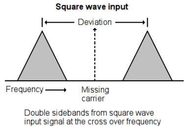
The square wave frequency should be set to the pre-emphasis cross over frequency in case of PAL this about 750kHz, for NTSC about 500 kHz with a input level of one volt peak to peak into 75 ohms.
For 18MHz bandwidth Carson's rule stats you are able run a maximum 2.5 MHz deviation taking in to account the highest sound carrier frequency at 6.5 MHz. We now have workout that this is party true, Only 250 kHz is the maximum amount of deviation that sound sub-carriers will be generating. There for, for given bandwidth you are able to run a wider deviation than what Carson's rule will indicate when working with FM TV.
Final alignment:
There is not a lot to done at this point, all you need for test gear is HF frequency counter good up to 10MHz or an Oscilloscope and go through these steps.
1/ At R9 and at the input of the 6MHz ceramic filter is the test point for the 6MHz oscillator. Hook your frequency counter and adjust VC1 until the frequency reads the wanted frequency. Repeat this process for R16 on the 6.5MHz ceramic filter and adjust VC2 in the same way.
2/ Connect the frequency counter to the prescaler output, set to divide by 256 by shorting out JP2 with the header jumper. Then read the output frequency and multiply that by 256 to work out the TX frequency.
3/ Set VR6 for minimal gain and then adjust VR5 for the VCO range.
4/ Apply video signal to video input, that is set for one voltage peak to peak into 75 ohms. If you have the ability to display colour bar this is a good pattern to set levels to. Adjust VR6 to set the deviation and trim VR5 for the operating frequency.
5/ Add your two audio signals the inputs and adjust VR1 and VR2 to set the sound deviation.
6/ Set VR3 and VR4 for sound injection level, adjust until you are just below point of inter-modulation. This take will the form of wavy lines appearing across the display video.
That’s it you are now ready to go on the air and give ATV ago.
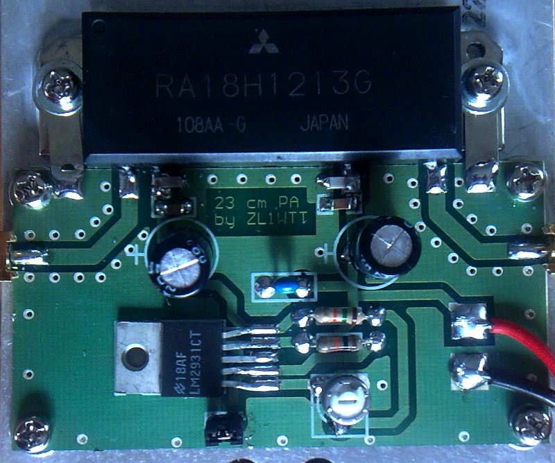
I also have a 23 cm power amplifier board available for those who interested using a Mitsubishi FET based power block the RA18H1213G.