
Digital ATV testing with COFDM (DVB-T)
Background:
Coded Orthogonal Frequency Division Multiplexing (COFDM), this format is used for terrestrial broadcasting on VHF and UHF frequencies. With the cost of digital television modulators coming down, there is now far better ways to transmit digital amateur television (DATV). The bad old days of last century are now behind us and we now can move on with these new digital modulation systems. In New Zealand we have so little UHF spectrum available to use, we now need to share 10MHz at 70cm with low power devices and amateur narrow band users. Now we have a real problem trying to fit 20MHz of spectrum down into just 10MHz.
Testing:
I wanted to find out what was possible with COFDM and how it would be affected with narrow bandwidth signals. The first problem was finding an amplifier that was linear enough to work with the 8k mode. The only module that I had that I could make use of was a Harris UHF driver amp that I got from Mike (WA6SVT). This driver operated at 32v at 2A DC to provide 1.2 Watts out of RF, as you have already worked out, it gets quite warm. So the simple rule to remember with COFDM works out something like 10 to 1 ratio for VSB rated amplifiers (ie 2kW analog amp would provide 200W of average power with digital modulation).
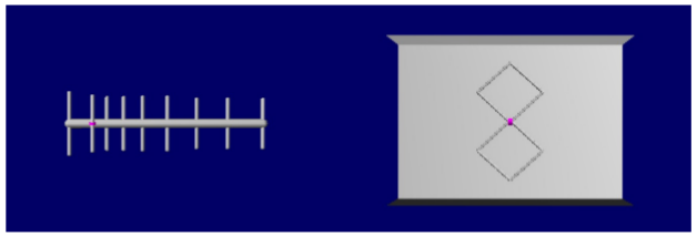
To compensate for the low RF power output I needed to design a high gain Yagi to maximize effective radiated power (ERP). On a narrow bandwidth FM voice receiver you don't know that anything is there, it just sounds like white noise. There is also no impact with FM voice repeaters due to tone access blocking any noise from been re-transmitted, weak carriers don't have any real effect on the DATV signal from the forward error correction (FEC) rebuilding the missing data. If you key up a transceiver next to the COFDM receiver it just goes into overload (inter-modulation) and ends up with no signal. DATV can be used in the same band as other users; this is done by separating wide band from narrow by using horizontal and vertical polarization. This is why UHF/SHF band-plans show narrow bandwidth repeaters as vertical and DX and ATV modes as horizontal.
The frequency we used for testing was 434MHz to fall within the center of the 70cm band (standard 8MHz channel). I tried out a number different configuration with Ian (ZL1VFO) to get feel for how much carrier to noise that we would require over the three modulation levels.
The signal to noise I measured at Ian's home location was about 16dB, he had good success with both QPSK and 16QAM. But 64QAM was just holding in on his set top box with a few break ups.
COFDM receivers:
Televisions and set top boxes normally cover the frequency range of 174MHz to 860MHz; all new televisions sets on the market now have COFDM built in and therefore making it easy to receive DATV on 70cm. Some of the problems we ran into were from older Set top boxes that would only work with Mpeg2 and standard definition. Using my Sunray DM-800SE 3 in 1 (DVB-T, S, S2 and C) with this receiver I could transmit high definition using h.264 and AC3 sound without any problems. You can also buy set top boxes out of China for very little cost. Depending on the model you can get extended VHF frequency range from 48MHz through to
868MHz.
I am currently designing a 33cm down converter that will be able to have low enough phase noise to down mix to VHF. I hope to do testing on 900MHz in the New Year (2014). I would expect to get similar results on this band as well.
The next step:
I am now in the process of getting in a 250W Harris UHF power amplifier from Mike (WA6SVT) to operate on 70cm, I would expect about 25W of RF power for COFDM. Then I plan to repeat these experiments with Ian at this higher power level, to see what impact this will have on the band.
Channel bandwidths:
There is a 2MHz channel as part of the DVB-T format, but it is near impossible to find a receiver that will demodulate this bandwidth. The only device I know, that is able to work with 2MHz are the USB dongles, which limits things somewhat. So the only channel bandwidths I could test were 6, 7 and 8MHz. I found that 6 and 7MHz did not work as well as I expected and found that a lot of television sets were fixed at 8MHz.
Again same old problem is working with outdated band-plans and trying to fit everything in. This why a lot of what I do is experimental and this is how I get around this problem.
Aerial designs:
As well as designing a 12dBi Yagi, I am in the process modeling a 13dBi Bi-Quad as a possible repeater transmitter array that has a wide pattern. The one I'm currently working with is made up out of parts from an old VHF high band TV antenna. I cut down and reused the elements as well as the folded dipole. On the right is the RX or TX panel that I plan to put together for testing at a later date. A Bi-Quad as the name suggests is just two Quad dipoles stacked with reflector behind and fed via a 50 ohm quarter wave balun.
Coded Orthogonal Frequency Division Multiplexing (COFDM), this format is used for terrestrial broadcasting on VHF and UHF frequencies. With the cost of digital television modulators coming down, there is now far better ways to transmit digital amateur television (DATV). The bad old days of last century are now behind us and we now can move on with these new digital modulation systems. In New Zealand we have so little UHF spectrum available to use, we now need to share 10MHz at 70cm with low power devices and amateur narrow band users. Now we have a real problem trying to fit 20MHz of spectrum down into just 10MHz.
Testing:
I wanted to find out what was possible with COFDM and how it would be affected with narrow bandwidth signals. The first problem was finding an amplifier that was linear enough to work with the 8k mode. The only module that I had that I could make use of was a Harris UHF driver amp that I got from Mike (WA6SVT). This driver operated at 32v at 2A DC to provide 1.2 Watts out of RF, as you have already worked out, it gets quite warm. So the simple rule to remember with COFDM works out something like 10 to 1 ratio for VSB rated amplifiers (ie 2kW analog amp would provide 200W of average power with digital modulation).
To compensate for the low RF power output I needed to design a high gain Yagi to maximize effective radiated power (ERP). On a narrow bandwidth FM voice receiver you don't know that anything is there, it just sounds like white noise. There is also no impact with FM voice repeaters due to tone access blocking any noise from been re-transmitted, weak carriers don't have any real effect on the DATV signal from the forward error correction (FEC) rebuilding the missing data. If you key up a transceiver next to the COFDM receiver it just goes into overload (inter-modulation) and ends up with no signal. DATV can be used in the same band as other users; this is done by separating wide band from narrow by using horizontal and vertical polarization. This is why UHF/SHF band-plans show narrow bandwidth repeaters as vertical and DX and ATV modes as horizontal.
The frequency we used for testing was 434MHz to fall within the center of the 70cm band (standard 8MHz channel). I tried out a number different configuration with Ian (ZL1VFO) to get feel for how much carrier to noise that we would require over the three modulation levels.
The signal to noise I measured at Ian's home location was about 16dB, he had good success with both QPSK and 16QAM. But 64QAM was just holding in on his set top box with a few break ups.
COFDM receivers:
Televisions and set top boxes normally cover the frequency range of 174MHz to 860MHz; all new televisions sets on the market now have COFDM built in and therefore making it easy to receive DATV on 70cm. Some of the problems we ran into were from older Set top boxes that would only work with Mpeg2 and standard definition. Using my Sunray DM-800SE 3 in 1 (DVB-T, S, S2 and C) with this receiver I could transmit high definition using h.264 and AC3 sound without any problems. You can also buy set top boxes out of China for very little cost. Depending on the model you can get extended VHF frequency range from 48MHz through to
868MHz.
I am currently designing a 33cm down converter that will be able to have low enough phase noise to down mix to VHF. I hope to do testing on 900MHz in the New Year (2014). I would expect to get similar results on this band as well.
The next step:
I am now in the process of getting in a 250W Harris UHF power amplifier from Mike (WA6SVT) to operate on 70cm, I would expect about 25W of RF power for COFDM. Then I plan to repeat these experiments with Ian at this higher power level, to see what impact this will have on the band.
Channel bandwidths:
There is a 2MHz channel as part of the DVB-T format, but it is near impossible to find a receiver that will demodulate this bandwidth. The only device I know, that is able to work with 2MHz are the USB dongles, which limits things somewhat. So the only channel bandwidths I could test were 6, 7 and 8MHz. I found that 6 and 7MHz did not work as well as I expected and found that a lot of television sets were fixed at 8MHz.
Again same old problem is working with outdated band-plans and trying to fit everything in. This why a lot of what I do is experimental and this is how I get around this problem.
Aerial designs:
As well as designing a 12dBi Yagi, I am in the process modeling a 13dBi Bi-Quad as a possible repeater transmitter array that has a wide pattern. The one I'm currently working with is made up out of parts from an old VHF high band TV antenna. I cut down and reused the elements as well as the folded dipole. On the right is the RX or TX panel that I plan to put together for testing at a later date. A Bi-Quad as the name suggests is just two Quad dipoles stacked with reflector behind and fed via a 50 ohm quarter wave balun.
Digital modulation modes use within COFDM:
There are three formats used, as shown below. Where information is modulated in both the phase and in amplitude domains, two bits of data is sent per symbol (change of state) for QPSK, four bits for 16QAM and six bits with 64QAM.
There are three formats used, as shown below. Where information is modulated in both the phase and in amplitude domains, two bits of data is sent per symbol (change of state) for QPSK, four bits for 16QAM and six bits with 64QAM.
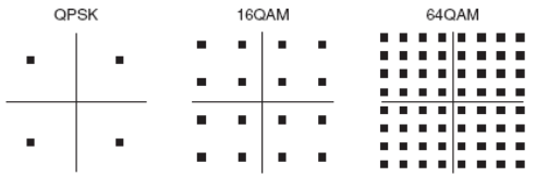
With COFDM alongside these three levels of modulation you also have different carrier modes such as 2k, 4k and 8k. This sets the number of modulated carrier to transmitted in a set channel bandwidth, this is where the term orthogonal comes from (more than one carrier been sent). Guard band intervals operate within the time domain by leaving a space for any reflections to fall within. This is why COFDM has very good multi-path characteristics.
Modulation
type
|
Coding rate
(FEC)
|
Guard
interval
|
|||
1/4
|
1/8
|
1/16
|
1/32
|
||
QPSK
|
1/2
|
4.976
|
5.529
|
5.855
|
6.032
|
2/3
|
6.635
|
7.373
|
7.806
|
8.043
|
|
3/4
|
7.465
|
8.294
|
8.782
|
9.048
|
|
5/6
|
8.294
|
9.216
|
9.758
|
10.053
|
|
7/8
|
8.709
|
9.676
|
10.246
|
10.556
|
|
16QAM
|
1/2
|
9.953
|
11.059
|
11.709
|
12.064
|
2/3
|
13.271
|
14.745
|
15.612
|
16.086
|
|
3/4
|
14.929
|
16.588
|
17.564
|
18.096
|
|
5/6
|
16.588
|
17.564
|
19.516
|
20.107
|
|
7/8
|
17.418
|
19.353
|
20.491
|
21.112
|
|
64QAM
|
1/2
|
14.929
|
16.588
|
17.564
|
18.096
|
2/3
|
19.906
|
22.118
|
23.419
|
24.128
|
|
3/4
|
22.394
|
24.882
|
26.346
|
27.144
|
|
5/6
|
24.882
|
27.647
|
29.273
|
30.160
|
|
7/8
|
26.126
|
29.029
|
30.737
|
31.668
|
The interesting thing is that not all digital modes are equal, as you can tell from the graph below. The factors you need to take into account for a DATV repeater is the amount of data you would like to send vs the carrier to noise. The colored dots show FEC ratios of 1/2, 2/3, 3/4, 5/6, 7/8 and the impact this has on the data throughput vs signal to noise ratio.
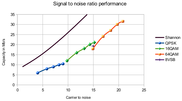
Where 8VSB is fixed at 19.3 Mb/s, unlike COFDM that has an advantage of setting the mode for your data requirements. Another thing to remember when it comes to carrier to noise is that 10dB could be the difference between 100W and 1kW of RF power that needs to be transmitted.
Shannon-Hartley theorem tells the maximum rate at which information can be transmitted over a communications channel of a specified bandwidth in the presence of noise. The closer you can get to this line the greater the efficiency of data vs bandwidth. This is where the next generation of COFDM will provide improved performance (DVB-T2 16k and 32k modes).
Shannon-Hartley theorem tells the maximum rate at which information can be transmitted over a communications channel of a specified bandwidth in the presence of noise. The closer you can get to this line the greater the efficiency of data vs bandwidth. This is where the next generation of COFDM will provide improved performance (DVB-T2 16k and 32k modes).
In summary:
ATV is all about finding the best way to receive noise free pictures, with digital it comes down to how close you can get to the noise floor and finding the best modulation system to do this. Out of all the digital modulation systems I have experimented with, COFDM has had by far, the best overall performance for the transmit side of a DATV repeater. Sending DATV from the home station DVB-S (QPSK) has advantage due to the fact that you are only working with one modulated carrier. By doing this, the power amplifiers do not need to have the same amount of linearity as you would with COFDM. With the 70cm band in the US been 30MHz wide and 20MHz in Canada, this form of DATV repeater would provide greater coverage over current ATV repeaters designs.
ATV is all about finding the best way to receive noise free pictures, with digital it comes down to how close you can get to the noise floor and finding the best modulation system to do this. Out of all the digital modulation systems I have experimented with, COFDM has had by far, the best overall performance for the transmit side of a DATV repeater. Sending DATV from the home station DVB-S (QPSK) has advantage due to the fact that you are only working with one modulated carrier. By doing this, the power amplifiers do not need to have the same amount of linearity as you would with COFDM. With the 70cm band in the US been 30MHz wide and 20MHz in Canada, this form of DATV repeater would provide greater coverage over current ATV repeaters designs.