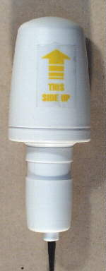
 The Temp / Humidity Sensor - :
Microcontroller file can be found here.
The Temp / Humidity Sensor - :
Microcontroller file can be found here. 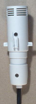
| |
Input-output ports (P2, P3) (8 bits) | : | Pull-up (pull-down) resistor input or high- impedance input, CMOS output or NMOS open drain output: these can be specified for each bit; external 0 interrupt |
| |
Input port (P0) (4 bits) | : | Pull-up (pull-down) resistor input or high- impedance input; external 1 interrupt |
| |
Output port (P1) (4 bits) | : | CMOS output or NMOS open drain output |
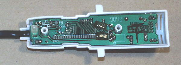

 Schematics