 Tait T700 Packet Mods
by ZL1VFO

Tidying up my shack, I decided to make a bit more 'proper' radio and TNC setup.
As I had several T700s about not doing anything, I decided to press these into service with an Opentracker2 and USB uTNT Plus TNCs.
The USB uTNT Plus TNC was adapted first, however I couldn't find the command set to set up the Tx audio levels.
It looks like the USB uTNT Plus TNC doesn't have a 'CALibrate' command, and I wasn't able to find the command list of what it did support.
So I decided to modify the radios to suit - i.e. the Tx Audio to control the radio's FM deviation.
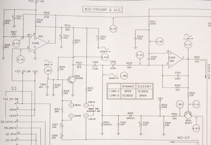
Looking at the T700 schematic, we see a mic pre-amp circuit.
As we have way too much audio from the USB uTNT Plus, I decided to bypass the preamp and fix the gain of the ALC in the following stage.
R316, a 1k surface mount resistor was disconnected. R316 connects to the inverting op-amp input on the left (pin 2 of IC306), and helps set the gain of this stage.
A 12k resistor in series with a 4.7uF electrolytic capacitor was joined between 'Link 1b' and pin 2 of IC306.
This set the transmitted 1200/2200 Hz packet tones used to about 3.5kHz deviation for the high tone.
Lowering the 12k resistor value will increase the TV audio deviation, and increasing the resistor will drop the Tx deviation.
One pad of R316 was used and the 'Link 1b' pad for the electrolytic negative connection.
This board is rear one of the removeable T700 head - the one with the black DB15 socket poking out the back.
See photos below.
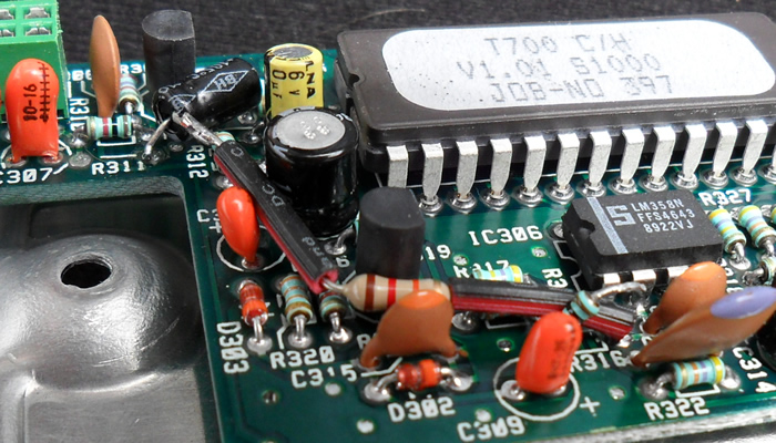
R316 is in front of the small IC on the right, behind an orange tantalum, and has it's right leg lifted.
The 12K resistor is soldered into this hole.
'Link 1' doesn't exist, but the electrically same spot is the right hand side of where R311 would be if it were there.
The Electrolytic negative goes to that terminal on the far left of the photo.
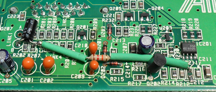
This particular version uses different circuit references.
R316 is called R211, and is the third component in from the bottom right.
R211 is moved aside, & we connect to the pad which is closest to the op-amp IC above.
'Link 1' has it's 'B' terminal circled on the far left.
Electrolytic negative goes to that terminal.
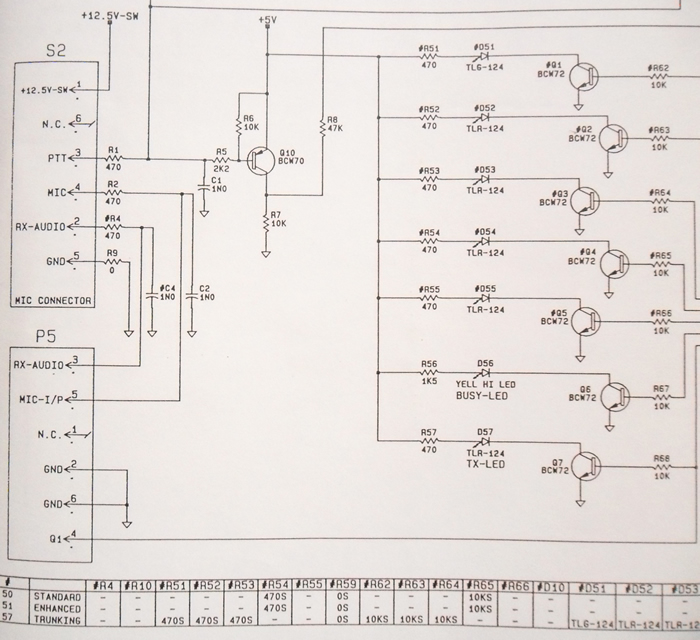
Looking at the circuit for the display board with the integral mic socket, the 6-pin P5 connector has RX-AUDIO available on pin 3.
It then passes through R4, a 470ohm resistor, to pin 2 of the Mic socket (S2).
But no, looking at the chart at the bottom left of the photo, R4 is not present in any of the three versions listed there.
So we have to add it.
See Photos below.

In this photo, P5 is at the top, and the black mic socket at the bottom.
R4 is not present - it needs to be fitted next to C2 near P5.
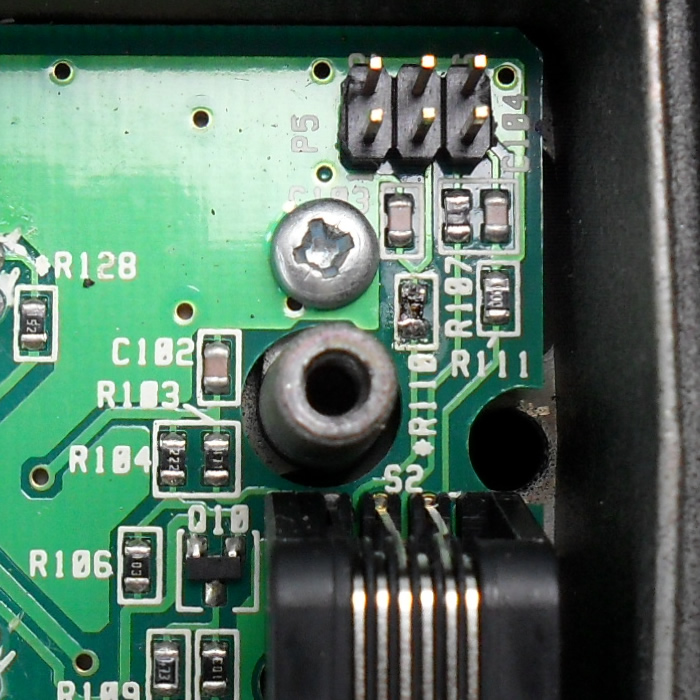
This version is similar, again P5 is at the top, and the black mic socket at the bottom.
R4 is now called R110 and has been fitted, near the screw and the post.
The Mic socket then has the following useful signals
Pin 2 - Received Audio to the TNC.
Pin 3 - PTT line to the TNC - standard active low.
Pin 4 - Transmit Audio from the TNC.
Pin 5 - The Ground connection to the TNC
Current U.S.A Server Time and Date
Current New Zealand Time and Date
You are visitor number  since 18/09/1999