|
Philips/Pye FM-828U Repeater Conversion Instructions (ZL1KFM-001)
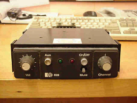 |
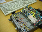
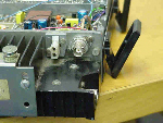
In the late 80's Philips brought out a Transceiver, in the form of the FM-828. The
radio came in many configurations, depending on it's use, from a single channel radio to a multi 10 channel. The one shown above is a 4 channel Transceiver. On the single channel radio, the channel switch is replaced with the squelch pot. The radio is also crystal controlled. After Philips was sold to Pye, the name on the radio was changed to reflect this (Now called a Pye FM-828). There are no differences to the radio except for the name. I have a number of the radios from both companies. Now for the good news, both Philips and Pye brought out a kit that allowed the radio to be turned into a STAND-ALONE REPEATER. However since the radio is no longer supported, the kits are no longer available, HOWEVER there is good news, that is that they can still be converted, with a few of the parts not installed, namely the antenna filter (note:- I have not had too much, if any desence, due to not using the filter, but do use a good Duplexer:)). These radios are still around, and come up quite regular. In my view I would not pay any more than NZ$60.00 for an un-converted radio. For a radio that has already been converted, I would look at paying around $100-$150.
The information below is mainly designed to convert the UHF (410-470MHz) range of radios, but could be used for the other bands, with some checking of the schematic. Goto the link for the FM-828A Transceiver, I have not done any of the VHF models as of yet, and can not confirm the details.
For information, I know they came out in FM-828A or FM-828B for VHF and FM-828U for UHF models, they also came out on a W1 and W2 band, but I have no information as to what these bands are. (See updated Information)
 Thanks to Barry, VK3SW for supplying the following information on the different models of "FM-828" Thanks to Barry, VK3SW for supplying the following information on the different models of "FM-828"
| Freq |
Model |
| 66-88Mhz |
"E" |
| 132-153Mhz |
"B" |
| 148-174Mhz |
"A" |
| 403-420Mhz |
"T" |
| 440-470Mhz |
"U" |
| 470-500Mhz |
"W1" |
| 500-520Mhz |
"W2" |
I have been informaed the "E" band version has been converted to work on 6mtrs. I have no experience on this conversion.
The "U"(May stretch), or "W1" model, using the internal switching would be suitable for "PRS Radio" which requires no external control.
There will need to be some minor component changes if converting a "FM-828U" model to above 470Mhz, download the FM-828 schematic, and the component details are included. "Download TIF File(161K)".
The repeater configuration would be dependent on your local RFS Department for PRS Repeater operations, contact them to ensure you are within the law. All details within these documents are for Amateur Radio requirements.
South Auckland Repeater Group, and others contributing information within this document, WILL NOT accept responsibility for breaching any local or Country laws.
It is YOUR responsibility to ensure your system is within the Law.
WARNING: - All modifications are
done at your own risk. I DO NOT accept responsibility to any damage caused to the radio, or equipment connected afterwards. I have taken the information from the original repeater kit, and modified it to incorporate the changes of parts no longer available. Every endeavor has been made to ensure the information is correct, However there maybe errors, and the odd spelling mistake may of slipped in also.
I have converted a few radios over using this information, and have had no problems, in the conversion, and the running of them.
If you wish to contact me, for further information, help or comments. Please e-mail me using the following link.
(Information: To prevent spam, the e-mail address has the following included "(spam_block)" this needs to be removed, or else your email will not arrive. Sorry about this, but it prevents spam searching software from finding the address, and sending spam to me.)
All photos can be displayed larger, by clicking on the photo.
All the best, and Happy Modifying -Kevin, ZL1KFM
(This page is Best Viewed in 1024 x 768)
Modifying Instructions
- Remove all wires from facility socket SK1, insulate end of each wire with 15mm of
heat-shrink sleeve and secure wires beside PS/A board (These will not be used). Remove the facility
socket SK1. You can remove the wires completely if the radio is not going to be converted
back, this will save heat-shrink sleeve each wire.
- Also, if you are not going to use the radio as a standard radio again, you can also
remove the wires from the Mic connector in the back, and remove the connector. (Again you
can remove the wires completely if you wish, however, keep the speaker wires). The vacant
hole can be used with a new connector (I use a Din 8 pin Socket and the old red insulator.
The red insulator will need to be reamed to accept the new Din socket), and then can be
used with a Repeater controller.
- Disconnect receiver coax from pins 7 and 3 on Tx. PA Board, and pull back into the PS/A
area. Be careful not to damage the cable in any way.
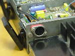
- Re-route cable through hole vacated by facility socket and terminate coax into the
centre pin of the new BNC socket, and the braid to a earth solder lug as close to the
socket as possible. Secure the socket
to the radio body. (I use a chassis mount socket and
the Mic socket. I cut the mic socket down and use it to hold the BNC socket, I then mount
it to the vacant facility socket, secured with the mounting screws. Some super glue
prevents the BNC turn turning.
- Fit an extra earth point opposite Pin 8 of the audio power supply board using a solder
lug, M3 x 6 screw and washer, into tapped hole in chassis. Remove small piece of
insulation from Rx coax and solder shield to earth lug.
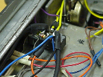
- Remove the two brown wires on the AUX switch LHS, connect together and sleeve. (For
versions fitted with CTCSS, also remove the brown/black and grey wires, connect together
and sleeve)
- Link Channel 1 on both the Transmit and Receiver boards. (If using a multi-channel, I
would recommend disconnecting the channel switch and hard wiring it as a single channel
radio).
 |
 |
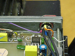
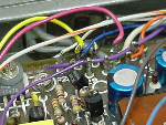
Modification to Exciter Board
- Fit 100K horizontal preset (119) into board beside microphone sensitivity preset (R108)
- Fit 22K resistor in R120 position (adjacent to Pin 30)
- Run yellow wire from Pin 30 (Ex) to AUX switch (through ferrite bead at switch end) to
LHS rear terminal. (Remove and sleeve brown wire on Pin 30)
- From centre terminal LHS of AUX. Switch run a yellow wire to the top of volume control
(behind mounting plate)
Modifications to PS/A Board
- Remove and sleeve orange wire to Pin 4
- Fit 47uf/6v tant. Between Pins 29 and Pin 3 with +ve to Pin 29
- Connect a pink wire from Pin 29, behind Volume mounting plate, to front terminal RHS
AUX. Switch.
- Remove and sleeve yellow wire on mute pot LHS terminal.
Modifications to Receiver Board
- Replace R124 (470E) with a wire link
- Cut lead near top of R117 leaving 1-2mm lead. Remove the cut lead from the board. Solder
a diode (1N4148) with cathode towards the board in the lead hole. Solder the other end to
the top of R117
- Solder a short length of pink wire to link Pin 34 and Pin 26. (Remove and sleeve purple
wire on Pin 34)
- Fit sleeve link on track side between L16 and L13 cans (passes over Pin 8 track) to tie
earth tracks together
- Fit 4N7 between junction of R98 (27K) and TR22 collector (+10v rail) and the ground
track connected to L17 and L18 can. Solder capacitor on track-side of board using heat-shrink sleeve
on each leg with earth lead solder to unused junctions of AFC components.
- Fit 10nf bypass capacitors on Pin 35,36,37,38,39, and 40 to ground on track-side making
leads as short as possible. It will be necessary to remove the solder resist in five
places. (Multi-channel versions only).
- Fit ferrite bead to blue wire on Pin 12 and secure with a drop of glue (Evostick or
similar)
- Remove and sleeve yellow wire on Pin 29
- Using a red wire, make a connection between Pin 8 and Pin 9
- Connect a red wire from Pin 8 to mute pot. Route the wire in the receiver compartment as
much as possible.
- Remove blue wire from Green LED, and connect to rear terminal RHS AUX. Switch. Make
another connection from this point via a 470E resistor to the Green LED.
- Fit a 1N4148 diode between front and centre RHS terminals of AUX. Switch with cathode to
centre
- Fit a ferrite bead over each wire to the multi-channel switch (except centre earth
connection) and place bead so they are as close as possible to the exit hole between Ex
and RX compartments to provide isolation between both areas. Secure with glue.
CTCSS Options (ST104 CTCSS)
- Disabled - Remove and sleeve lead to PS/A board Pin 33
- Encode Only
- Remove and sleeve lead to PS/A board Pin 33
- For sets fitted with no CTCSS, shift the yellow wire from the LHS centre terminal of the
AUX. Switch to the LHS front terminal. Solder a 1uf tant. Capacitor between the centre and
front terminals with +ve to centre.
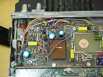
- Fit shield over PS/A board. Insert small lip between EX board retaining springs and
chassis. Shield is held securely in place by top cover. (I do not do this, and it works
okay)
For External Connection Socket (Using Din 8 Pin Socket, for connecting to a controller) - Not Part of the
Standard Repeater Kit, Developed by Kevin, ZL1KFM
- Solder centre connector of one piece of RG-174 coax to Pin 4 of the External Socket This
is the TX audio into the Radio. Route cable along and into the Tx compartment to the AUX
switch (I run mine in front of the Squelch pot or Channel switch). Cut back the braid of
the free end and cover (sleeve), with the centre connector coming out. Solder the centre
connector of the free end to the RHS front pin of the AUX switch.
- Solder centre connector of a second piece of RG-174 coax to Pin 5 of the External
Socket, This is the RX audio out of the Radio. Join the two braids together and solder to
Pin 8, and the chassis earth tab. Also route the cable along and into the Tx compartment
to the AUX switch. Solder a black wire to the braid of the free end and cover/sleeve, this
will be soldered to an earth point later. Solder the centre connector of the free end to
the RHS rear pin of the AUX switch. Now solder the black wire to an earth point. (I use
the rear connections on the Power switch).
- Solder a Blue wire to Pin 7 of the External Socket, this is the COS out from Radio, 0v-
Active. Route wire into Tx compartment and solder to LHS rear connector of the AUX switch.
There will be 2 wires and one resistor soldered to this connector. COS is controlled by
the front panel Squelch control.
- Solder a Purple wire to Pin 3 of the External Socket, this is the TX(PTT) input to
Radio. Route wire along the back wall of the radio and solder to Pin 29 of the PS/A Board.
Pin 29 has a time-out built-in the radio for 3min approx. For set-up's that require the
Time-out to be removed, solder the Purple wire to Pin 22.
- If you wish to add CTCSS output triggering, solder an Orange wire to Pin 2 of the
Exterminal Socket, and solder the other end to the CTCSS Decoder board trigger output..
- One last job, drill a hole near the new External Socket to accept a 3.5mm speaker
socket. The best way I found was to glue it into position. Solder a Brown wire from the
centre connector of the speaker socket to PS/A board Pin 28. Solder a Black wire from the
earth connector of the speaker socket to PS/A board Pin 3. The speaker is controlled by
the main volume control, and will not effect the audio for repeater operation.
Alignment
- With AUX. Switch 'out', align set as per the manual.
- With AUX switch 'in', apply a 1mV P.D. with 1KHz/3KHZ dev. Signal to the Rx aerial
socket. Set deviation of the retransmitted signal to 3KHz using R119. (Disable CTCSS
Encode function for this operation by temporarily shorting EX Pin 45 to ground).
Operation
If the radio has been modified with the External Socket, you have two modes of
Operation.
- Mode 1
AUX Switch in the "Out" position, the radio will
operate from the External Socket connection, from a Repeater Controller. If the radio is
not modified with the External Socket, and still has the Mic Socket, the radio will
operate as a normal 2-way Transceiver.
- Mode 2
AUX Switch in the "In" position, the radio will
operate as a stand-alone repeater. No external connections are required. For some
Countries this mode may breach area regulations as no Id'ing is done.
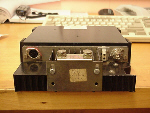
The Finished Back
Repeater Kit Parts
| 1 x |
BNC Socket, (preferably Chassis Mounted) |
| 1 x |
Din 8 Pin Socket |
| 1 x |
100K horizontal preset |
| 1 x |
22K Resistor |
| 1 x |
470E Resistor |
| 1 x |
4N7 |
| 1 x |
47uf/6v Tant |
| 1 x |
10nf Cap. (1 for each channel, multi-channel) |
| 2 x |
1N4148 Diodes |
| 2 x |
300mm Lengths RG-174 mini coax (may be longer) |
| 1 x |
300mm Length Blue wire |
| 1 x |
150mm Length Orange wire |
| 1 x |
100mm Length Purple wire |


Web Site designed using the following software:

CoffeeCup HTML Editor |

1st Page |
|

Milonic Menu |
Web Designer - Kevin Mitchell, ZL1KFM
(Remove "(spam_block)" from the addressee before sending e-mail)
Copyright © 2004 [Sth. Auckland Repeater Group]. All rights reserved.
Revised: February 25th 2004
.
|