Using a GPS Reference
This is also a viable option, although a little more expensive. The unit will happily lock to 1pps pulses from a GPS module which supports this option. The performance is similar, and consistency of results is better than TV if a good GPS setup is used. I don't claim this unit offers anywhere near the performance of either commercial or recent Amateur dedicated GPS Disciplined References.There is another approach which should work beautifully. If your GPS unit has a 10kHz output reference, (for example the Rockwell Jupiter is one of these), you can divide this output down to 50Hz or 100Hz and use it to lock the unit. Simply drive the ICP pin (pin 11) of the micro without the sync separator. The unit will lock successfully to any integer fraction of 2kHz.
Another very good solution if you have a good OCXO reference, is to divide that to 50Hz and lock to that. I recommend building the 5MHz Reference version for this purpose, since it provides 50Hz output (to phase lock the transmitter) and includes the sync separator and phase detector for monitoring (but does not lock your OCXO reference). The advantage of this approach is that you can set the OCXO calibration off-air, or operate the system with a very noisy Rubidium-based TV video source, or even no video at all, if you are confident of the OCXO performance. Use the same PC monitoring software for both micros. Two micros are always better than one!
No, there is no way to lock the unit to the NMEA serial data from a GPS unit. This data does not have sufficient timing accuracy.
Using Other References
Provided the reference can supply an exact division of 2kHz between 100Hz and 10Hz (e.g. 100, 50, 25 or 10Hz) at 5V CMOS level, it should work. The gain will change if you use other than 50Hz, so you may need to tweak the PLL control algorithm. Simply connect the CMOS/TTL 5V level drive to the ICP pin (pin 11) of the micro. The risetime needs to be good, and of course the precision source should have very high stability, preferably 1 part in 108 or better.If you don't live in a CCIR/PAL TV country, don't despair! This unit will also lock well to the 60 Hz frame reference of a Rubidium-locked NTSC composite video signal. You may need to tweak the time constant in the sync separator, but most likely it will work fine with the suggested values. Since the oscillator phase is under-sampled, there are a number of possible reference frequencies. You have two choices:
- Introduce an extra divide-by-six stage between the sync separator and the micro ICP input (pin 11), so the unit samples at 10Hz. Everything else will remain the same, but the lock time might be slightly longer. A CD4017 will work fine as the divider. Connect the "6" output to the RESET, so that it counts from 0 to 5, and use the "1" output as the ICP input.
- Change the firmware so that the step resolution is 1800Hz or 2400Hz, rather than 2000Hz. This will mean no hardware changes, but you will need to change the "milliseconds" counter to divide by 900 or 1200 in order to keep time of day correctly. With the different step resolution, the choice of "round number" operating frequencies is not as convenient (but you can for example still operate at 3600kHz, 3750kHz or 3900kHz for example).
No, you can't use the unit to generate colour subcarrier, or to lock to the colour subcarrier. The frequencies need to be related to the 50 or 60Hz reference by a simple mathematic ratio.
Using the Super-Stable Exciter as a Transmitter
This is what the Super-Stable Exciter for HF was designed for! You will need a power amplifier (I suggest no more than 5W output), which in turn suggests an amplifier with at least 20W rating (since few amplifiers can handle continuous operation). The PA of an old commercial or Amateur HF SSB transceiver would be ideal. These usually have the necessary sensitivity and gain. Since the Exciter output is +13dBm (-17dBW), you'll need a gain of about 25dB to achieve the required power level. If the gain is any higher, use a pad between the Exciter and the power amplifier. At 5W average output, the PEP output will be 20W (on the ticks).I use a Codan power amplifier, which has plenty of gain, and I have 33dB of attenuation before the amplifier input for 5W output. At power levels higher than 5W it can be very difficult to keep the RF out of the video. One solution there is to break the DC path from the Exciter to the transmitter, by floating the output BNC connector above earth. High powered ICAS linear amplifiers throttled back for CCS operation are very inefficient, and require fan cooling and large power supplies.
Another problem is that, because it is operating on the output frequency, the phase-locked VCXO tends to pull when you operate a higher powered amplifier. Mount the Exciter in a fully shielded box, but be prepared for trouble!
I also designed a special Class C Power Amplifier for the purpose, which is much simpler and far more efficient. It puts out 2.5 Watts for a total consumption of 5W, and can run from an unregulated 12V supply. A modest heatsink is used, with no fan, and continuous operation for weeks on end is assured.

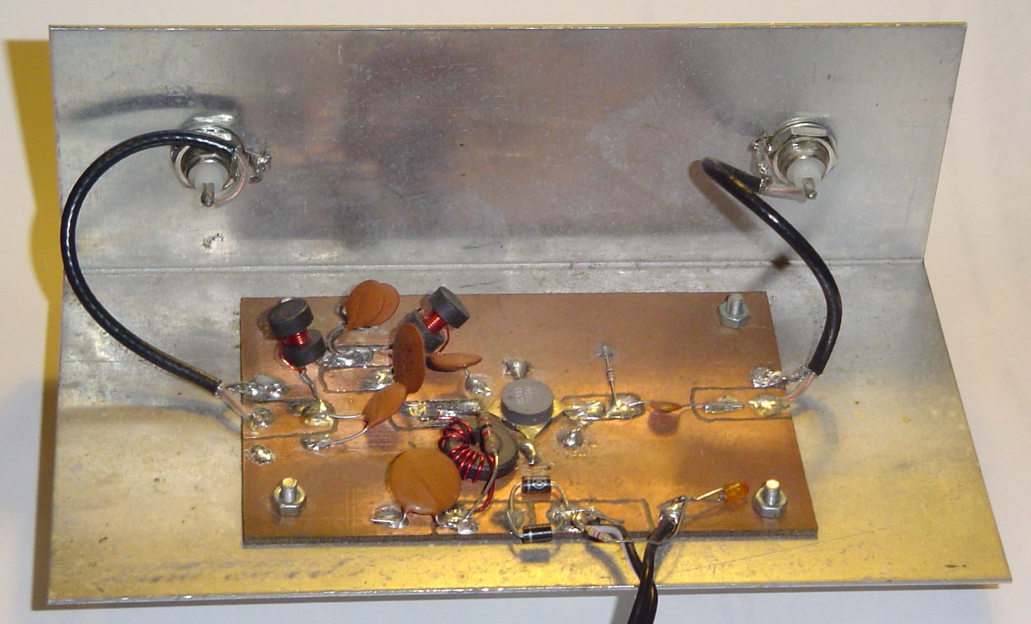
The simple 2.5W Power Amplifier
You MUST use a band pass or low pass filter between the Exciter and any linear amplifier, and a low pass filter in the power amplifier output. I suggest a low pass 50 Ohm halfwave filter as the filter between the Exciter and the linear amplifier. If you use my Class C amplifier, you should not use the filter before the amplifier, as it relies of square-wave drive. The amplifier includes its own very effective output low pass filter.
The filter I built to this design has a 3dB frequency of 6MHz, and a notch of -45dB at 10MHz. The ultimate attenuation depends on construction, but should exceed 30dB above 20MHz, and more than that between 10 and 20MHz. I suggest using a small box made of copper laminate with BNC connectors. The Power Amplifier is built in the same way and benefits from the same performance. A sheet of 1.6mm Aluminium about 100 x 200mm provides more than sufficient heatsink for the power transistor. To use the amplifier and filter on other frequencies, either recalculate the filter component values from the impedances quoted, or simply scale the values given for 3850kHz.
Be aware that in the 'nostalgia' firmware version, the 1kHz modulation of the Exciter is square-wave, so if the signal is at all strong, the ticks will be heard up and down the band 10 kHz or more. If this is a problem, either turn the ticks off, or use the tick signal from the micro (pin 8) to generate a sinewave and use an external modulator, for example a double-balanced mixer or high level AM modulator on the Power Amplifier. I doubt if the key-clicks from carrier keying will be a problem, but for high power use, the keying signal (micro pin 8) can also be used for external keying via a suitable click filter. The spectrally 'clean' version is clickless and very narrow under all circumstances.
Another thing to consider is that you MUST ensure that the transmission does not interfere with your TV reference! For example, if you put the Exciter on the air without any filter, the higher harmonics of the output (which extend way up to several hundred MHz), can degrade TV reception seriously. If this is a big problem, even with good filters, reduce power, repair your TV antenna, try a different TV receiver, or give up and use a good OCXO to control the transmitter, and calibrate the OCXO off-air, perhaps using the 5MHz version of the firmware and another micro.
Using the Super-Stable Exciter as a Local Reference
You can use the unit as a local reference, for example for calibration, to lock your frequency counter, or as a reference for an Amateur TV timing chain. Obviously in these applications the tick modulation and Morse ID capability is not required, and you may need to add a divider or TTL buffer device to the output. The usual frequency choices for such applications are 5MHz and 10MHz, and this unit will do the job just fine at these frequencies.There is a special version of the firmware intended for 5MHz operation. It has no modulation capability, or CWID, but has precise 1kHz, 50Hz and 1Hz outputs. However, you would be much better off building the GPSClock design, which will operate with any just about any voltage controlled TCXO or OCXO.
If you need a 1MHz reference for a frequency counter, it is better to operate at 5MHz or 10MHz and use a divider on the output than to operate at 1MHz, as it may be difficult to achieve sufficient pull range on a 1MHz crystal. There is no need to use an oven-controlled crystal, although if you also intend to use the reference without the TV network, (switch SW1 in the FREE position) a good TCXO or OCXO with voltage control will be helpful. The VCXO control voltage range is 0 - 5V, and a control range of at least �2 parts in 106 is expected. If the control range is less than this, carrier noise is reduced, but the time to lock is much greater. The VCXO frequency should go DOWN as the control voltage goes UP.
Quality of Reference
While you may not have much choice, make sure that you use the strongest, cleanest signal for your TV reference source. It is important that the signal be noise-free, and especially interference-free. If the signal is at all noisy, the phase performance of the Super-Stable Exciter will be degraded. The noisy signal example shows what happens when the signal is strong but degraded by interference. In this example, the unit remains locked, but exhibits phase noise of around �1Hz. If you look closely at the main display, the blue phase line has noticeable noise, and the white frequency line has been thickened. In this respect, this design is way better than simple hardware phase lockers (which generally use the line frequency), and no doubt the noise performance could be improved further with digital filtering, at the expense of lock time. Perhaps a switchable hardware loop filter (added after lock) would be a solution.The TV station used for phase lock MUST be using a Rubidium timing reference, or all the effort is wasted. In New Zealand, use TV1 or TV2. In Australia, use an ABC station. Anywhere else, you will need to find out for yourself which networks are locked, and what their behaviour is. For example, some networks go off the standard at night while they transmit canned infomercials (during this time they run calibration sessions on their studio equipment), or may simply run an unlocked pattern generator. Other networks go off-standard during outside broadcasts. I recommend operating off each station for some time in order to check their behavour. Operate the Exciter on dummy load and follow the phase on the PC software.
A disused video recorder makes an excellent video source. The power consumption is much lower than a TV receiver, and no high voltages are involved. Potentially the recorder could also power the Exciter. All you need is the tuner, receiver and video output. The rest can be non-functional. When tuning up, check the quality of the video on an external monitor. After that, you won't need the monitor.
In general, you'll get much better performance if you use a GPS receiver with 1pps output as the reference source. The 1pps output will have excellent low jitter (but make sure you use a good GPS antenna).
Construction
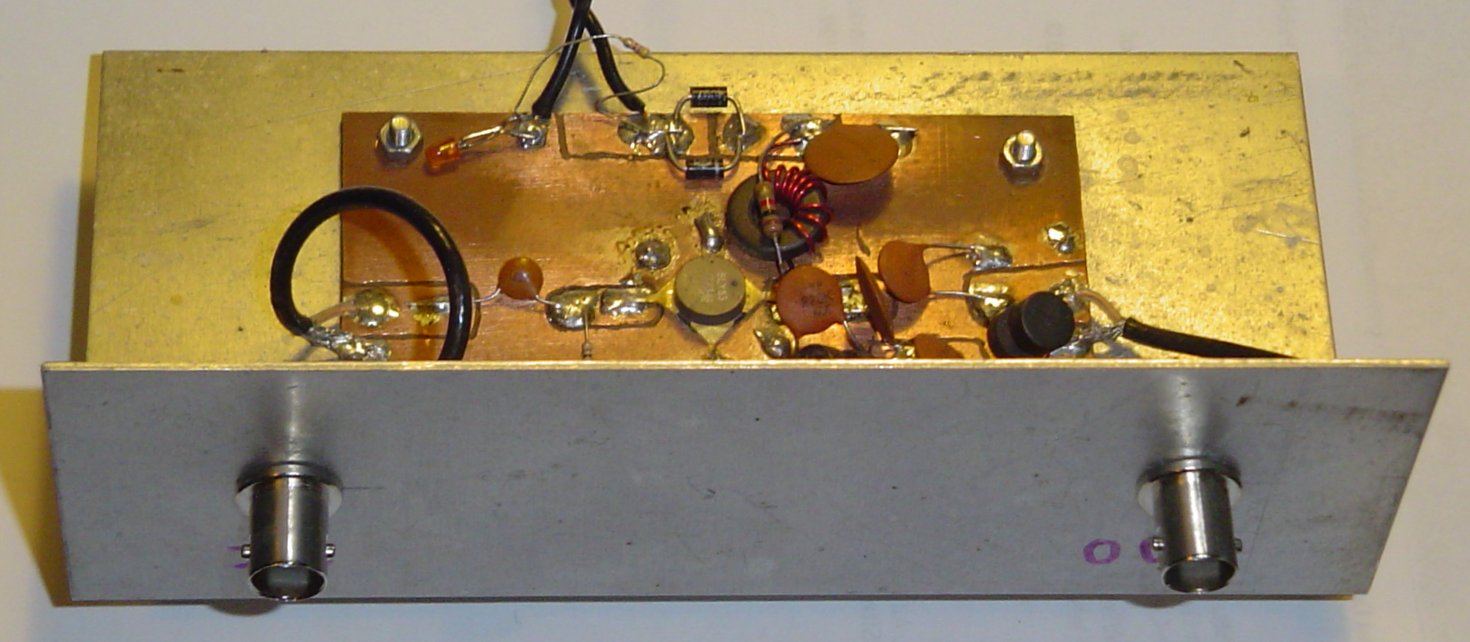
The Super-Stable Exciter is best built in a small (120 x 90 x 50mm) diecast box. This provides good RF shielding to prevent leakage of micro and reference signals, prevents ingress of strong HF transmitter signals, gives a rugged construction platform, and provides a relatively stable thermal environment for the reference. The circuitry can all be built on a small project board, the type with pre-drilled holes and copper spots on the back. A board 90 x 50mm should suffice. Secure the finished board to the box with metal pillars and bolts. Rugged construction is important. Take a look at the prototype:
A view inside the prototype unit
In the above picture, the three control switches are top left on the front panel, and under them is the RF output. On the right at the top is the reference video input connector with the DC power connector behind it, and below these the RS232 connector. Above the circuit board in the centre is the reference crystal in its socket, securely bolted to the box via a standoff. On the circuit board, which is a small Dick Smith project board, the micro U2 is in the centre, with the 74HC00 device U3 to the left. Near the crystal are the varicap diode D2 and the trimmer capacitor C2. At the bottom right is the sync separator U4, with the 5V regulator U1 and the RS232 interface transistors above it. The ugly thing in the bottom of the box is the programming header, in this case on a short cable, taped up to prevent shorts. This unit needs no backup battery as it is powered by an external 12V 7AH battery.
A 5MHz non-phase locked version can be built in a smaller tin box (remember wedding cake tins?) with feedthrough insulators in order to keep the noises in and the RF out. Couple the clock input to the OCXO with coax, through a low capacitance feedthrough, and use coax and 1nF feedthroughs on power supply and ALL the outputs. This way the OCXO can run and be monitored on a 24 hour basis without jamming reception of WWV!
The switches used in the prototype are excellent miniature 1P3T switches with centre off. These look like conventional miniature switches, but have a central third position which connects to nothing. Other switches could be used, but the solution would not be as elegant (more switches would be needed).
If changes of frequency are planned, then fit a good reliable crystal socket and use HC6U crystals. Preferably fit a clamp (even a rubber pad on the lid) to hold the crystal in place. None of the components, apart from the crystal, are especially critical.
Here is a list of some of the more interesting parts:
Ref       Type                  Description
C2        Trimmer cap           Air-spaced, 3-30pF
C3        Capacitor             Silver Mica, Polystyrene or NPO ceramic
D2        Varicap diode         Approx 20pF 0V - 5V; 1N4756 (47V zener) works fine
L1        Transformer           Small ferrite core, 8 turns:8 turns
L-        Inductor, filter      Choke in add-on filter; 7T on small ferrite bobbin
U1        Regulator             78L05
U2        Microcontroller       Atmel AT90S2313-10PC
U3        HCMOS gate            74HC00
U4        Sync separator        National LM1881
X1        Crystal               Fundamental mode 25�C, 30pF parallel load
Understanding the PC Software
The PC software is a DOS executable compiled using Microsoft Quick Basic. It is a graphics program, and whether you run it from DOS, Windows 3x or from Windows 9x, it will generally need to run full-screen (Windows cannot always support different graphics resolutions and settings on different parts of the screen). There are no commands to the the Super-Stable Exciter from this software. This is to make sure that you can't mess up the time keeping. It does however show the time. To set the time, you need to use Windows Terminal or something similar, and do it off air before you get started, as the commands affect phase lock.The PC software display has four functional areas -
Main Phase/Frequency
At the top is the main large phase/frequency display. It shows two things --
The current phase in blue (actually only about 90� range since the typical variation when
in lock is usually only 10� or so). There are no calibrations shown, but the resolution is about 0.35�
or two radians.
- The accumulated frequency error is shown in white, with blue fill back to the correct frequency (looks cool). The display is calibrated if the operating frequency is set correctly in the setup file. The centre line represents the exact frequency, and the other two dotted lines represent 1 part in 108 error. Frequency error is accumulated over very long time intervals, and becomes more accurate with time. This display isn't much use when locked, as all you get is a straight white line (or at least you should!), but is useful for checking drift and thermal effects of the unlocked (FREE) VCXO or in unlocked OCXO versions. The operating frequency and frequency offset are also displayed above the display in text form. The resolution is 0.1 parts in 109.
The default time frame of this display is one minute per pixel, so it takes around 12 hours to cross the screen. The frequency calculation is integrated for increasing accuracy across the width of the screen and resets when the screen clears. Frequency calculation will therefore be slow to arrive at the correct value if there is a large initial phase error, so reset the display (F5) once the unit is locked or the unlocked offset is low.
The operating serial comms port, data rate of the PC software, and the operating carrier frequency, are predefined in the file REFMON.SET. This file is also used to indicate whether the unit being monitored is a 'locking' or free-running type, although all this does is suppress the 'LOCK' indication on the screen for the free-running version where it would make no sense. The operating frequency only affects the calculated frequency offset at the top of the screen and the gain of the frequency line on the main display.
-
The current phase in blue (actually only about 90� range since the typical variation when
in lock is usually only 10� or so). There are no calibrations shown, but the resolution is about 0.35�
or two radians.
Knowing when the TV Network is 'On Reference'
Ahah! I thought you might want to ask that one! The first thing to do is find out from those in the know what the normal operating schedule of your TV network is. If you can't find out, you'll need to monitor for a week or so to find out for yourself. If you are lucky enough to have two TV stations with Rubidium standards, you can compare one with another. My favourite local station seems to be well behaved, staying on its reference for days at a time. But then, it rarely does outside broadcasts.When 'On Reference', the PC display will show an almost straight line for the slow phase plot (the blue line) over a period of many hours. Slow changes should be due to thermal effects in your crystal. However, watch you don't bump the unit, as crystals are sensitive to mechanical effects which will cause minor phase shifts.
Unexplained jumps can be caused by mechanical shocks, RF in the video, or poor reception, but watch out for loss of power supply regulation or a flat battery. Most likely unexplained jumps will be caused by the network being 'Off Reference', or rather the reference changing occasionally from one less than accurate source to another. If the fast phase display has considerable jitter, suspect poor reception (noise or interference).

Noise on the fast phase display caused by poor reception
If the TV network goes 'Off Reference' for a time, it will usually be for five minutes or more, and will cause a step in the phase response. Once they are back 'On Reference', the phase will go back to where it was before. Once you are confident of when they are 'On Reference', write down the phase value your unit uses. It should be the same, or at least close, whenever their Rubidium/GPS reference is used. Keeping track of your unit in this way will also be beneficial in assessing the ageing rate and summer-winter variations of your crystal. The lock range is from 0400HEX to 047FHEX, and the value should stay most of the time at around the centre of this range. If the value wanders toward one end or the other over a period of months, the frequency will still be OK, but the risk of loss of lock is increased. Just tweak the trimmer capacitor C2 occasionally to bring it back. See the Calibration Information step 4 for details.