How would you like a 40 MHz frequency counter for under $50? What if I told you it also had
an 8 digit LCD display, optional offsets for use in a receiver or transceiver, 10 Hz
(even 1 Hz!) resolution, and also a six channel digital voltmeter built in?
Direct reading with prescalers in the VHF version? Oh, and optional PC telemetry so you
can watch the output on a PC, log the results, or graph drift? Well, read on!
COUNTER SPECIFICATIONS (all models)
CIRCUIT DESCRIPTION
COUNTER OPERATION
PRESCALER
COMMUNICATIONS

Maybe all you are looking for is a low power digital display for your homebrew QRP
rig? Well the receiver software version of the counter has programmable IF offsets
and an S-Meter display thrown in!
This design is something of a kitset of different bits for you to experiment with.
The VHF version can select divide by 10 or divide by 64 prescalers and provide
direct reading. This counter uses an older AT90S4433 device, now superceded by the
pin compatable and largely code compatable ATMEGA8.
While this design is
capable of doing all the things described, it is more intended as a test bed for your own experiments
than as a dedicated bench-top counter. If the latter is what you need, see the newer
High Performance Frequency Counter
design.
The counter contains only three inexpensive ICs (well, add a regulator and three transistors),
and operates from 6 - 15V DC at about 25mA. The most expensive single item is the LCD display,
which is an industry standard 16 x 2 dot matrix module, which can often be found used or at
bargain prices. This isn't a kitset, but the parts are easily obtained, and the circuit can
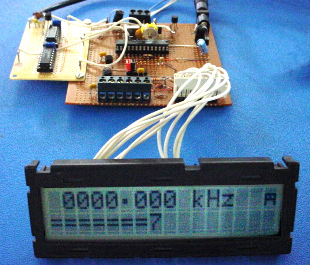
be built using any prototyping technique, or you could design your own PCB. The prototype was
built on a small commercial strip board.
View prototype full size
Some of the features of the unit are:
- Four ranges, with 10 Hz and 1Hz resolution to at least 40 MHz.
- High sample rate (5 samples/sec or more) with averaging to remove jitter.
- Programmable � offsets and S-Meter display for receiver or transceiver.
- Binary and BCD maths to provide direct reading of frequency with prescalers.
- Low current single supply operation. Can be operated from a small battery for portable use.
- Optional high speed PC telemetry.
- Well documented source code is available, so the design can easily be adapted.
Features of the PC telemetry application provided are:
- Six A-D channels and high resolution counter channel.
- Graphical colour display on the PC, with digital display, bar-graphs and a trend graph.
- PC display completely configurable independently on each channel.
- Channel data type, gain, offset, and measurement units can all be preset.
Software for counter consists of firmware (executable code) for the AVR processor,
and a graphical application for the PC. You can purchase just executables or the
source code, and either way you get the code for both AVR and PC.
See the Micro Page
for details.
The PC software is a DOS executable which will operate
directly from Windows™ 3.1, 95, 98, XP or 2000.
It will usually operate full-screen, but as it is a graphics application,
your computer may not allow operation in a "DOS BOX". The software can also be run directly
from DOS. A VGA screen and a 66 MHz processor or better is required.

The PC software screen
Click on image to view full size
Look closely at the PC display. In the upper box you see the colour legend at the left,
followed by the data for each channel in HEX, then the scaled and converted decimal value
with full precision, and finally the bar graph for each data channel. The bar graph has
limited resolution. The software commands are indicated below, and finally at the bottom
is the trend graph.
Although not easy to appreciate from the picture, the trend graph is very powerful.
All the data channels are displayed using their
characteristic legend colour. The range of the graph is 0 - 255, so all the results are
scaled to fit. The exception is the frequency trend, which is displayed twice. The white
trace is the same as the other channels (effectively 0 - 10 MHz, resolution 40 kHz),
but the multi-coloured trace has high 10 Hz resolution, and a span of 2.55 kHz.
In high resolution mode the span is 255 Hz and the resolution an incredible 1 Hz.
As the signal frequency drifts to move off the top or bottom of the display, it reappears
back at the bottom or top. You can see this clearly on the
display snapshot. The counter was monitoring a signal
generator while the frequency range was changed. The drift (over 2 kHz in perhaps
10 minutes) is clearly visible.
By adjusting the scaling and offset in the setup file, any narrow frequency range can
be followed using the white frequency trend graph.
The timebase (horizontal speed) of the trend graph can be set to one dot every four
samples (SLOW) and one dot per sample (FAST). As the counter mode changes, the trend
graph speed automatically adjusts to suit the sample rate.
Use CNTR.BAS as a guide to writing your own software, or to adapt
CNTR.BAS for your own purpose. Notice that the source code is not very large or complex.
To recompile the software as a DOS executable, you will
need Microsoft Quick BASIC 4.2 or another advanced BASIC compiler. (GWBASIC and
similar interpreters are too slow).
The configuration file CNTR.SET is used to set the Channel Number, "Channel Name", Units, scaling (division factor), and offset for each of the channels. It also sets which PC serial port is used.
This file can (and should) be edited by the user to suit individual applications. There must be
seven lines of channel data.
Unused channels have "" as Channel name, but must have a Channel Number. Unused channels
will not be displayed. The numbers can be in any order. The Com Port line must not be omitted.
Any port 1 - 4 is valid, depending on the existence of the port, and whether your BIOS will
support it. Use COM1 or COM2 to be on the safe side.


 HOME
HOME