Commissioning
the
Southern Avionics SC1000 DGPS USCG Dual Transmitter
Introduction
The SC1000 transmitter drawer is fully self-contained, and apart from connecting up a source of power and drive,
can be operated without any of the rest of the transmitter equipment. This is not only the easiest way to check
out the transmitter, but is also the most appropriate way to use the equipment for Amateur purposes. The following
discussion assumes you will be using it in this way.
The transmitter is suitable for operating on Amateur bands from
130 to 530kHz, with appropriate changes to the drive frequency and the Low Pass Filters. The transmitter is capable
of up to 1000W, given an appropriate (rare!) antenna. 400 - 500W is more typical. It can be on-off keyed, FSK modulated,
and even AM modulated.
The transmitter is extremely efficient 550W in for 500W out), very rugged, and extremely forgiving when antenna
problems occur. I've never had a semiconductor failure.
These DGPS transmitters are fairly rare, and you're unlikely to encounter another one. However, the NDB transmitters from the
same company are very similar. There's not enough component information provided here for you to build a copy
(inductors especially would be a challenge), but
it would be a very attractive proposition, and all the schematics are available. All you need to run a homebrew version
is a 110V 1000VA transformer and a small 18V transformer.
Initial Checkout
You will need the following equipment:
- A modest oscilloscope and 10x probe
- A 200W (at least) 50 Ohm dummy load
- A Digital Multimeter, 20V and 200V AC and DC voltage ranges.
- An exciter (preferably the ZL1BPU LF Exciter). At the very least, a VFO
or signal generator with 0dBm into 50Ω capability.
Later you will need:
- An LF antenna, say a Marconi Tee or inverted L, with a good system of buried ground radials
- A loading coil of huge proportions, about 2mH maximum, adjustable
- A 2.5A current transformer type RF Ammeter
- Preferably a good RF RX Bridge (able to measure resistive and reactive components)
You will also need all the following schematic drawings. Save them locally and then print them out:
- Transmitter Drawer Interconnections
- RF Driver
- DMOD Driver Modulator
- SPA Switching Power Amplifier
- PA Power Supply
- Low Pass Filter
- KWRF (SWR Sensor)
- MDC Module Disconect
- Monitor
- AMTR2 SWR Meter
- Interlocked Power Control (ZL1BPU)
- Simplified block diagram
First, check that all the transmitter modules and plug-in boards are available, and install one set of transmitter modules
(DMOD Modulator, SPA Power Amplifier and LPF Low Pass Filter), the Driver board and the Monitor Control board. Remove the other transmitter modules for now.
Switch OFF the front panel RF ENABLE switch (to DISABLE). This disables the modulators. Switch the MONITOR switch to DISABLE.
 Apply 24V DC to TB1 at the rear of the transmitter (+24, TB1/8: 0V, TB1/7. TB1/6 may also be 0V). The fan will start up,
lights will appear on the front panel, and the 24V power supply current should be well under 1A. At the power supply
modules (on top of the big electrolytics) check voltages on the terminal strip TB2, nearest the front of the transmitter in each case.
Referenced to the chassis, the 4th terminal from the front (TB2/3) should be about 24V (depends on your supply).
The 6th terminal (TB2/1) should be 12V �0.5V. There should be nothing on other terminals.
Apply 24V DC to TB1 at the rear of the transmitter (+24, TB1/8: 0V, TB1/7. TB1/6 may also be 0V). The fan will start up,
lights will appear on the front panel, and the 24V power supply current should be well under 1A. At the power supply
modules (on top of the big electrolytics) check voltages on the terminal strip TB2, nearest the front of the transmitter in each case.
Referenced to the chassis, the 4th terminal from the front (TB2/3) should be about 24V (depends on your supply).
The 6th terminal (TB2/1) should be 12V �0.5V. There should be nothing on other terminals.
Apply drive at the rear BNC connector. 200mV p-p (0dBm) is quite enough, and sine or square will work. Do not exceed 1V RMS.
It is best to start with a frequency 200 - 300kHz. The ZL1BPU LF Exciter or one of the DDS Signal Generators
from the same designer would be ideal (use the DIRECT output from the R-2R network).
Switch the FOLDBACK switch (top right of the Driver board, see below) to the right. You'll need to leave it there forever now.
Switch the MONITOR switch to DISABLE. As yet no suitable scheme has been devised to allow this circuit work correctly.
Now check some signals on the RF Driver board (front right, nearest the panel). TP0 (furthest left) is 0V, and
referenced to here you should find at least 200mV p-p of drive on TP5, and a 5V p-p square wave on TP3 and TP4.
Disconnect the drive for a moment - you should observe a square wave of roughly 30Hz on TP3 and TP4. Wind the top edge trimpot on this
board (R8) fully anticlockwise. Watching the DC voltage on TP2, wind the pot fully clockwise. You
should see it rise to 4V or so on TP2. Wind the pot back down again. (Soon you'll get tired of winding this pot and
likely replace it with a front panel one with a knob!
Next we check for RF drive at the SPA (transmitter) module. With no high voltage on, there's no output, but the drivers
are active. On the SPA module, (the one with four FETs on the heatsink, nearest the power supply),
check for 5V p-p square wave drive on TP2 (referenced to TP0), and 12V p-p on TP3 and TP4. These two are
at 180� phase difference, and must be exactly 50% duty cycle with fast risetime. There may be some slight ringing. If either
of these signals is wrong, you may well need to replace Q1, Q2, Q3, Q4 and U1. TP5 should have a messy-looking
12V p-p square wave. Switch off the power and remove the module when connecting or removing the probe. The
test points can be hard to see, and mistakes and slips can be costly!
Now we get brave and add some HV DC power to the transmitter! First, switch off, and temporarily connect 24V
to the HV DC input (TB1/5) as well as the LV input. On the power supply, the second terminal from the front (TB2/5)
should now have about 24V DC on it. Connect the meter to one side of the fuse on the SPA module. (You
can use the front panel meters, but at this stage you may not know what to look for).
Switch the front panel RF ENABLE switch to ENABLE. The LED should come on. Wind the trimpot R8 on the driver board
SLOWLY clockwise, and observe that after a few turns the meter voltage should rise, indicating that the
DMOD (Modulator) is working. Stop when you get to about 12V. If you don't get to 12V, switch off and check the DMOD
by replacing it with another one.
There should now be significant RF output. By playing with the meter switches, you should be able to measure
the SPA voltage and current. Both should be quite low (10V, under 1A). If all is well, switch off, swap to
the other pair of modules (SPA and DMOD) boards and check them out too.
Now, with only one module set installed, is a good time to identify which module set is which.
Modules (1) are at the FRONT, and use the REAR Low Pass
Filter and the RIGHT Combiner transformer. The opposite is true of Modules (2). Check that the current and voltage
readings are indicated properly with left SELECT switch in the correct position. If the readings are zero,
switch the left switch to select the other module. The switch may need to be turned upside
down to make sense.
Real Power!
Individually check out the other set of transmitter modules as described above. Then install both sets of transmitter modules.
You can't operate with just one set at a time as the Combiner is not designed to
allow this to happen without some simple modifications. We'll fix that later.
Repeat the previous test, checking both transmitter module sets by switching the SELECT switch back and forth.
Remember that the RF ENABLE switch enables and disables the DMOD, and so removes
power from the PA board. For initial tests, use this switch to key the transmitter. Apply 24V (to LV and HV),
switch to ENABLE and wind the trimpot fully up. Check the meters on the front. The PA voltages should be about 22V
and you should be able to run up to 1.5 or 2A on both modules. The current should be similar (within 20%) on both modules.
By now you should have real power generated, about 50 - 80W into the dummy load. You can read this on the
top (Power) meter in the FRWD position. There should be very little in the REFL position.
If the currents are very different from each other, or are both very high or very low, switch off and check out continuity through the Low Pass Filters and combiners. Did you remember to connect the dummy load? Is there a short in your coax? Are the boards plugged in correctly?
Now we come to applying the high voltage. It's best to do this a little at a time, perhaps with a transformer with secondary taps,
say 50, 70, 100V, or a 110V isolating transformer with a Variac™ controlling the primary side. You'll need a 100VA transformer
or so. Stay with the 24V DC bench
supply for the LV input now, but disconnect it from the HV DC input. If you don't, you could blow up your
power supply.
Wind the Driver Board trimpot R8 back to zero (you'll get tired of this soon!)
Connect the HV AC inputs to TB1/1 and TB1/2. Power up the 24V DC first, then apply the HV power. You can check the
HV supply voltage at the second terminal from the front on the power supply output terminal strip (TB2/5). You should have
about 1.4 times the RMS AC voltage supplied. Wind that dratted trimpot up slowly, and after a couple of turns
the power output should rise. Increase until you reach about 100W (10%) on the FRWD meter. Check that the REFL reading
is almost zero - certainly well under 50W (5%). The current in each SPA module should be under 2A, and they should be
within 20% of each other. The voltage on the meter for each module should be the same, and about 30V for 100W output.
Before we set up the big power transformer and run real power, we need to make some mods to make the transmitter
safe to use, by providing interlocked front panel power control.
Transformer Control
It's not a good idea to apply LV and HV power at the same time, which is what would happen if we used just the windings
on the big transformer and switched the primary. In the complete transmitter LV and HV power are controlled by relays powered and operated
by the Controller unit. We need to power the relays from our big transformer for maximum convenience.
See the accompanying Interlocked Power Control circuit.
Two 24V DC relays
are required, at least one with 250V 10A contacts. Appliance relays are ideal. One relay controls the LV AC winding (red transformer wires, numbered 5 and 6). Using crimp lugs, appliance wire and a large screw terminal block, connect one
LV winding end to TB1/3, and the other to TB1/4 via the relay NO contacts, connecting the transformer winding to the COMMON point. Do the same with the HV secondary (white wires,
numbered 7 and 8), via the other relay and connect to TB1/1 and TB1/2.
You will need to build two simple DC supplies for these relays. Each consists of a 100uF 35V capacitor, and a 1N4002 diode.
Ideally these components and the control side of the relays can be on a small project board. The LV relay is arranged to switch from the front left switch (AC ENABLE). Connect one end of both relay coils to
ground (TB4/2). Connect the other end of the LV relay coil to TB4/5 (AC CTRL). Connect the other end of the HV relay coil
similarly to TB4/6 (DC CTRL).
Here comes the tricky bit! The anode of the LV relay supply diode connects to the COMMON side of the LV relay contacts
(so it has 18V AC all the time). The cathode connects to a 100uF 35V electrolytic capacitor (+ end of course), while
the - end is connected to ground (TB4/2). The junction of diode and capacitor connects to TB4/3 (AC CTRL+V).
The anode of the HV relay supply diode connects to the NO side of the LV relay contacts (so it has 18V AC only when the AC
relay is active). The cathode connects to a 100uF 35V electrolytic capacitor, while
the other end ,is connected to ground (TB4/2). The junction of diode and capacitor connects to TB4/4 (DC CTRL+V).
Wire the power transformer primary using another really big terminal strip. Connect power cord earth to the frame of the
transformer using a really big lug. Connect primary winding (black) wires 2 and 3 together, and to nowhere else;
apply the LINE side to wire 1 and NEUTRAL to wire 4. No fuse is needed, but a good quality domestic 10A circuit breaker
would be appropriate. It would be a good idea to add a good 10A line filter in the primary after the circuit breaker,
which can also act as the mains switch.
Switch all the POWER control switches off (down). Plug in the transformer. Wind that dratted trimpot down again.
Apply drive and dummy load. Switch on the circuit breaker.
Switch the left (AC) switch ON. The appropriate LED should come on above the switch, and the fan and DC circuits
should activate. Next switch the centre (DC) switch on (it should not switch on without the AC on).
The house lights may dim briefly as it switches on and charges the big capacitors. Finally switch on the right (RF)
switch and adjust the trimpot for say 200W into the dummy load. Everything should run completely cool (except the dummy load). After an hour or so the power transformer may be a little warm. This is normal.
Each module is capable of in excess of 500W, but for maximum reliability, 500W total is plenty. The maximum voltage
allowed on the SPA modules is 105V, and the maximum current in each 7A. It is not a good idea to operate into a
resonant load much above 60Ω as the transmitter than prefers to run at higher voltage and lower current.
This stresses the insulation in the output and combiner transformers. If the antenna is adjusted correctly,
60 - 70V and 4A is typical for each module. The transmitter is extremely efficient, and 500W total output will result
with these input values.
Switch-off should take place in the reverse order. Finally unplug the transformer from the AC supply.
It's not a good idea to apply power and activate the RF switch
with no drive - the transmitter will be safe, but will generate wideband pulsed noise. It is not a good idea to
key the drive without keying the DMOD stage. This problem is handled correctly by the ZL1BPU LF Exciter, which keys
the drive, but also keys the MOD at the same time, and sets the power level remotely.
The LF Exciter can
be powered from the 12V DC in the SC1000. Connect it to +12V from TB4/8 and 0V from TB4/7. This is a very tidy arrangement, as the
LF Exciter will come on and start the predefined beacon message on the predefined frequency as soon as power is applied.
If there's a power failure during operation, the power will be reapplied in sequence by the relay interlock,
and operation should continue happily.
Simple Modifications
That Pot!
The first thing to do is replace the RF Driver board trimpot R8 with an equivalent single-turn pot with a knob. It can stick up above
the board, and need not be front panel mounted, since the transmitter power can be remotely set. Use a quality plastic track pot
for smooth control. In the new arrangement (see next item) this pot simply
sets the maximum power, and it can be used to set power manually while testing.
Remote Modulation Input
In order to key the DMOD and control the transmitter power remotely, connect a wire from the junction of R8 and R25
to edge connector pin 4 (otherwise unused). Use fine wire-wrap or magnet wire. In the bottom of the cabinet, connect a
600mm length of RG-174 coax from edge connector socket pin 4 to a new BNC connector mounted on the back panel. Pick up ground from
edge connector pin 3. Label the connector MOD.
If you don't want to drill a hole in the panel, use a free socket on the end of the cable and poke it through the
large grommet in the middle of the back panel before connecting up to the edge connector socket.
Keying via the DMOD input is rather sedate (risetime 100ms or so), since it's normally used only to set power level.
For other modulation applications (including use with the LF Exciter), disconnect
electrolytic C7 on the RF Driver board. If AM operation is not contemplated, replace it with 1uF for nice soft keying,
or 100nF for ASK Hell keying. With no capacitor at all the risetime is about 500µs and keying is crisp, but not too broad.
AM Operation
With the RF Driver modified as described, i.e. with C7 removed and not replaced, the DMOD has a bandwidth of DC - 4kHz, reasonable linearity, 500µs risetime,
and modest phase shift. The transmitter can be very successfully AM-modulated, giving excellent clean audio! For AM, drive the new MOD
input via a 600 Ohm line transformer with the cold side of the secondary connected to 0V via a 10uF electrolytic.
Adjust power level with the pot R8 and the audio level to the transformer for correct modulation.
For remote power control, drive the 10uF capacitor just described from a 1k pot from a 5V supply.
If using the LF Exciter, simply feed the MOD input from the LF Exciter power control output via the line transformer secondary.
The extra capacitor is not required.
Modulation should be kept below 90%, as distortion creeps in as the DMOD output gets close to zero.
Some arrangement for carrier level control would be easy to arrange, increasing the DC level at the DMOD
input with increasing positive modulation, just as is done on broadcast transmitters.
Single Module Transmitter
A simple modification allows the transmitter to operate with just one module set fitted. You need to short the combiner
transformer of the unused transmitter. Dismantle the Combiner Mother Board and remove it from the cabinet. The card guide
securing screws help hold the board down, but before removing the nuts, tape the heads of the corresponding screws to the bottom of
the cabinet, as they're a pain to reassemble otherwise. Undo the screw terminals and lift the board out. To the right
(from the front) of each Combiner transformer is the footprint of a relay, fitted in some models. Fit fat pins in the
right-most pair of holes for each relay. Label (on the top) the left pair as DISABLE 2 and the right one as DISABLE 1.
Before refitting the mother board, wind the input and output screw terminals fully open, and use a small screwdriver to push
the internal contacts wide open again, or the stranded wires will be very difficult to insert correctly.
When you want to run just one module, remove all the other module boards (SPA, DMOD and LPF), and short the
corresponding combiner pins with a clip lead (to disable module 2, remove the boards for 2 and short the pins DISABLE 2).
The remaining module will be seeing ALL the load, which will look like 25Ω instead of 50Ω. It will
want to draw much more current than usual. Best keep it below 6A and the power below 200W. Operating in this way
is a handy way to check a repaired or doubtful module.
To permanently run with one transmitter, remove the combiner transformer for the module set you plan to use,
and short input to output. Then the module will see 50Ω and operate normally.
Low Pass Filters
For operation 180kHz to 300kHz, the original 450kHz filter will be quite adequate if a narrow-band antenna is used.
For operation below 180kHz, double the inductance of each coil and the capacitance of each capacitor in both LP Filters,
lowering the corner frequency to 225kHz. For operation to 530kHz, halve the values, raising the corner frequency to
900kHz.
Do not use ferrite cored coils. Arrange the coils so they do not mutually couple (as in the original LPF).
Always change all the coils and capacitors by the same ratio, so the filter
will work correctly at 50Ω impedance. For multi-band operation, make new circuit boards for the filters
so they can be plugged in as required. There are no other component changes required to change frequency, as the
transmitter is quite broadband. Check for excessive heating in the SPA and Combiner transformers at the lowest
operating frequencies, and if necessary reduce power.
It should be possible to use two different low pass filters and a switching arrangement to give a dual-frequency
500W transmitter capability with instant QSY. You will need to remove the combiners, add a relay to change output from
one module set to the other, and also arrange to separately enable the DMOD ENABLE inputs as you change bands.
If only changing the antenna over was as easy!
Kahn EER
The transmitter is capable of operating as a linear transmitter if the Envelope Elimination and Restoration technique
is used. This is sometimes called Polar Modulation (as opposed to Cartesian techniques such as phasing and I+Q).
For example, to operate PSK31, translate the audio PSK31 signal to RF using a mixer (best to use an I+Q Exciter
in order to avoid image problems). Drive the transmitter RF Input with the PSK31 LF signal at reasonable level (say +10dBm),
so that the envelope is removed by the squarer on the RF Driver board. Build a full-wave precision rectifier circuit to
recover the amplitude information from the PSK31 signal and use that to drive the MOD input. A dedicated PSK exciter
could also be built for this transmitter. No envelope modulation is required for FSK, MSK and MFSK techniques.
The propagation delays
through the SPA and DMOD are not the same, and so this technique will probably not work for SSB voice without unwanted
distortion, but by all means try it. Normally for voice and wideband applications based on this technique the modulator would have RF derived
feedback and feed-forward predistortion circuits, and there may be a Doherty amplifier operated in quadrature to help linearize the peaks. These techniques are widely used for MF and short wave broadcasting as they are very efficient at high power.
LF Exciter Drive
The ZL1BPU LF Exciter, using Version H firmware, will key the MOD input and control the transmitter power with the 'Pn'
command. In addition to illuminating the front panel LED whenever the RF is keyed on, the firmware sets the user selected
power level on a second D-A converter output with eight steps. When the transmitter is keyed off, the D-A output is set to zero.
The 'Pn' command can be used from the computer or set into beacon scripts, so the transmitter power can be
changed on the fly. When this new output is connected to the transmitter MOD input, the maximum output is about 4V.
To adjust the power level, first set the Exciter to mode M0, transmit (T command), and power level P0.
Set the pot R8 to minimum. Enable the transmitter (DC ON and RF ON), and set power level P7. Adjust R8 to the maximum
power level desired (say 400W, 40%), read on the FRWD power meter. Then check P6, P5, P4 etc, and note that the
power is reduced. Typically with 400W set at P7, P6 is about 300W, P5 about 200W, P4 100W, P3 50W, P2 20W, and P1 and P0
will give no output.
The new firmware also has a new DFCW mode, replacing the FSK mode. The new mode is called 'CASTLE', and is accompanied by
a new MAKEBCN message compiler for the PC. This new compiler allows the message script (text file) to include binary data
(such as HELL mode image data, JASON and power setting commands).
It automatically compiles all Morse family modes from plain text, and compiles all other commands, and then downloads
the message to the Exciter.
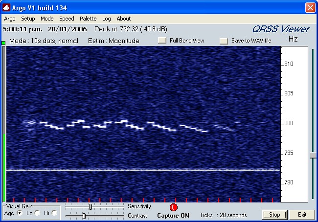
ARGO capture of Castle mode, 10 second dot mode
The above picture shows a 500km range capture of a daytime transmission on 181.4kHz using the SC1000 transmitter
and ZL1BPU LF Exciter. The distinctive message is in Castle mode, which is about 20% faster than DFCW, and 300%
faster than ASK Morse for the same dot length. The message reads
'BPU 76543', where 'BPU 7' is at 100W, '6' is at 75W, '5' at 30W, '4' (just visible) at 10W, and '3' at 2W (not visible).
The message was uploaded from a very simple script which starts with a 5WPM CWID, and reads:
$M1$LFB07$l$K000D$A03 DE ZL1BPU $M2$K0280 BPU7$LFB06$l6$LFB05$l5$LFB04$l4$LFB03$l3$LFB02$l2 ~
Antenna and Tuner Hints
Let's assume the plan is to use a Marconi Tee or L antenna, with a long top wire, or several top wires, and a modest up wire.
Make sure the top wire is well clear of or well above trees.
Use 10kV rated glass or ceramic insulators. Keep the top wire and up lead well tensioned and well supported,
as any waving in the breeze will cause detuning. The antenna bandwidth will be barely 2kHz when correctly adjusted.
The antenna will need a good ground setup, with buried radials.
More short radials (say 30m) are better than a few long ones.
Measure the capacitance between the antenna uplead and the ground (a simple capacitance meter will do). You should
have somewhere between 200 and 600pF, depending on the antenna size.
Calculate the inductance necessary to resonate this capacitance
at the operating frequency (say 2mH at 180kHz), and wind two bucket-of-wire coils on the outside of new 10 litre or 20 litre plastic paint
buckets (from a Plastics shop). Choose two different sizes if necesary so that one fits inside the other with a 2.5mm gap all around
to allow for the wire. Use heavy gauge insulated appliance wire, and close wind up from the bottom (narrow) end of the bucket. Secure
the ends with strong reinforced packing tape. The aim is to make each coil a little under half of the total inductance (say 800µH).
Mutual coupling will add the rest.
About 90m of wire will be required on each coil, and you may have to wind the coils several times to get the inductance right.
Then fit one bucket inside the other, and connect the coils in series so that they aid - you should easily get more than the required inductance through mutual coupling. The wire connecting the top of one coil to the bottom of the other must not lie across other turns.
Use extra insulation here. Mineral insulation is best (ceramic, glass-fibre, glass). The coils can be connected together
with one section cut from a 'chocky block' strip connector.
Using a system of wedges or packers, adjust the coil coupling for the correct inductance. A variometer is much easier to use for fine tuning
if you can manage one. Don't even think of using a tuning capacitor across the coil - this is a very lossy approach,
even if you use a high voltage vacuum variable capacitor.
Mount the loading coil well off the ground, connect the bottom of the coil to a 50Ω coax feeder from the transmitter
(grounding the screen of the coax to the ground radials). Connect the top of the coil to the antenna.
The next bit is easy if you have an RF RX Bridge. Simply adjust the bucket coupling until the X component is zero
at the intended operating frequency, and read the R component. Hopefully this will be well under 50Ω, indicating
good ground and low loss resistance. Without an RX bridge, you will have to painstakingly measure the SWR at the
transmitter in 1kHz steps over a wide frequency range in order to find resonance and move it to the correct frequency.
Using the ZL1BPU LF Exciter, you can also sweep the antenna through the transmitter. You can then detect the resonance from
the dip at the transmitter RF output, or a peak from a current probe temporarily placed between the coax and loading coil.
Without a bridge it is difficult to know whether the resonant impedance is above or below 50Ω, and so you may have
to try stepping the impedance up and down to see which is better.
The next step is to adjust the impedance to 50Ω. Several methods work. If you are lucky, and the feed impedance is below 50Ω,
you can simply use an L Network. Place a 1000V mica capacitor across the end of the coax where it attaches to the coil, and
increase the loading coil inductance to compensate. Adjust these values for best SWR at the transmitter.
If the antenna impedance is above 50Ω, you can't use this approach. Even if the impedance is lower, you may not wish to
use this approach anyway, as link or tap coupling has several advantages. First, ground the bottom of the loading coil. Connect
the coax output either to a tap say 6 - 8 turns up from the bottom of the coil, or to a 6 - 8 turn link around the
bottom of the coil. The link is best if the loading coil is made of insulated wire, as tapping is a pain. It also has
the advantage that the antenna current meter or current transformer can be in the cold end of the coil (between coil
and ground), and the transmitter ground remains independent of the antenna ground, best for QRM in the shack while
transmitting. The link should be made of heavy appliance wire.
While trimming resonance by adjusting the bucket spacing, adjust the link coupling (or number of turns)
or coil tap so that resonance occurs with lowest SWR at the transmitter. The transmitter should not be operated with REFL
power greater than 50W (5%) at any time, and antenna adjustments are best made with the lowest possible output power, at least
initially. Remember that body capacitance affects the tuning, and stay well away from the loading coil and antenna with power
on - there can be easily 5kV on the antenna, and serious burns can easily happen.
Another coupling method is to return the bottom of the loading coil to a tap on a large ferrite impedance transformer.
The transmitter is fed from another tap. This system allows a wide range of up and down impedance conversion.
The process of increasing power involves very careful adjustment and cautious increases in power. It is best done at night,
so background noise is least (so you can hear arcs and corona) and so you can also see any arcs or fires. Watch the REFL
meter like a hawk, and switch off pronto if it suddenly rises. Final adjustment of tuning should be done using a current meter.
A current transformer type is much more forgiving than a thermocouple ammeter. If you have one of these, use it ONLY to calibrate
the current transformer and its detector. A 2.5A FSD meter is a good size. It should be possible to achieve 2.5A into an efficient
antenna with 100W from the transmitter.
If the SWR suddenly increases as you inch the power up, you've probably reached the insulation limit somewhere. Unless you
can fix the problem, you'll need to drop power back to 3/4 of the final setting. If all stays stable after 30 minutes, you're
in business!
Each time you start a transmitting session, you will need to inspect the antenna, especially the insulators, check
for any trees touching or near the antenna, and then check the tuning at low power. Finally increase power as previously
described and check for arcs, corona and sudden increases in SWR.
Life is made a lot easier if the SWR meter is visible while adjusting the coil (remote the RF ENABLE switch as well), and if the current
meter is visible from within the shack. Despite the perceived convenience, don't mount the loading coil in the shack - it's
too dangerous, and you'll have to use special HV feedthrough insulators to connect to the antenna.
Copyright � M. Greenman 1997-2005.
All rights reserved. Contact the author before using any of this material.
HOME