ZL2AFP Clicklock
LF Propagation Measurement Tool
Introduction
Clicklock is a technique developed by Peter Martinez G3PLX. It enables a communications receiver to be calibrated automatically to receive LF signals with such precision that the carrier phase and power can be coherently demodulated and integrated over long periods.
The technique demonstrates sensitivity much greater than achieved using other techniques, and so signals previously considered undetectable can be detected and tracked to provide useful propagation indicators.
Measuring Phase
LF signals can't be assessed using HF techniques such as Doppler frequency measurement or radar-type ranging, for two reasons - the propagation mechanism is different, and the Doppler shift and signal bandwidth is too small to allow the techniques to be useful. LF propagation is a combination of ground wave, which travels long distances, and D-layer and E-layer ionospheric propagation, where the ionosphere acts something in the nature of a waveguide, since the height of the ionosphere is of the same order as the signal wavelength (measurable in kilometres).
Instead, two things can be usefully measured - signal strength, and signal phase. If the phase of the transmitted signal is known, the time of flight of the signal can be measured directly by measuring the phase difference from source to destination. To do this, a common phase reference is needed.
How does Clicklock work?
Communications receivers, even very good ones, have some errors as a result of unreferenced local oscillator phase and frequency. There's no easy way around this - even if the frequency is spot-on, there's no way to meaningfully measure the received signal phase because the oscillators in the receiver do not have their phase referenced to any world-wide standard. Nobody wants to hack into a receiver to modify the oscillators, even if it was practical to do so.
In addition, there can be phase variations that creep into a receiving system as a result of tuning variations in the antenna system, and different propagation times in the receiver on different frequencies and at different signal strengths. What we really need is a means of calibrating out (and compensating for) these receiver phase and frequency differences.
Clicklock is a PC sound card based system, and uses two versions of a universally available reference, the 1pps (1Hz) pulses from a GPS receiver. These pulses are generated from information received from the satellites, and have very high precision.
The 1pps pulse from the GPS receiver is fed directly to the PC sound card (the PPS Click), and the software uses this pulse to discover the exact location of a second event, the RF click.
The second version of the 1pps pulse is fed into the receiver antenna, where RF harmonics of the 1pps pulse are audible as a click, and can be analysed. Without going into complex maths, the phase relationship between all the harmonics in the receiver bandwidth will only be the same if the receiver is exactly on frequency, and in phase. If the frequency is slightly off one way, the phase of the harmonics will increase across the receiver bandwidth, or decrease if the frequency is off the other way.
The software uses Digital Signal Processing techniques (DSP) to analyse the phase of the harmonics in order to tune the receiver to the exact frequency, in the correct phase. It can't do that directly, since there is no communication with the receiver, so another DSP technique, the 'zero IF receiver' is used. A local oscillator in the software mixes the received audio down to zero frequency. This oscillator operates at the designated centre frequency (called the lock frequency). The phase of the zero frequency result is analysed and the software oscillator moved slightly in frequency and phase until all the harmonics line up in frequency and phase. In other words the whole receiving system becomes phase locked. When this happens, the receiver is ready to look for signals that are coherent with the receiving system (same frequency).
The receiver signals come in along with the RF click, and the software uses DSP techniques to determine the phase and amplitude of the signal, and to ignore the click products. The signal can be extremely weak, well under the noise, but by adding the samples together over a long time period, the signal samples continue to add, and the noise that comes with it tends to cancel out, since noise is random and has no phase coherency.
Coherent Reception
Coherent systems have been claimed in the past, but in reality they were at best time synchronized at bit level, NOT carrier phase and frequency synchronous. Repeated data can only be integrated to a limited extent, since after a time the signal phase wanders and the samples no longer add.
If however the carrier frequency and phase are analysed in a synchronous manner, it is possible to add samples (integrate them) for very long intervals of time, and have the signal build up and the noise cancel out. With a coherent system such as Clicklock, integration over HOURS is possible. This is like having a receiver with a bandwidth of fractions of a milliHz - and the stability to match.
The sensitivity offered is even better than using a Spectrogram (such as Argo) - probably by a factor of 20dB or more! This means that signals at least 40dB weaker than can be heard by ear can be detected reliably. It makes around the world propagation measurements possible, and allows measurements up to 1000km to be made with Amateur sized antennae and low power transmitters.
With really long integration times for the highest sensitivity, it isn't possible to send meaningful data, as the bandwidth is so low, but plenty can be INFERRED from the reception -
- Is the signal there? (fits an advertised schedule)
- What frequency is it on? (station A may be on one frequency, and station B another)
- What happens to propagation over the course of the day - can you work out where the sky wave propagation time is? From this you can know something about where the signal is from.
- What happens to the signal phase? Is it leading (reflective height lowering)? Does it jump suddenly (sky wave or ground wave predominates)? Is the phase reasonably constant (ground wave)?
- Is the signal coherent? (Either a standard frequency station or a specially GPS synchronized signal).
- Is the signal phase the same as yesterday at this time of day?
The system works best with signals that are transmitted on exact round frequencies (integer Hz). These are of course also easier to generate using GPS as a reference. However, the software has an additional fractional offset that can be added in order to operate with non-integer signals - but they must of course still exhibit very high stability.

Signals to Receive
Obviously it is best to use signals that will teach you something about the propabation path you have an interest in, and so should originate at or near the planned transmitting site, on or near the frequency of interest, and of course be GPS coherent.
There are numerous suitable commercial signals that can be used as test transmissions, but these may not be on a frequency of interest or in the required direction. The best examples are standard time and frequency stations, such as JJY (40kHz), many stations including MSF and WWVB on 60kHz, HGB (75kHz), DCF77 (77.5kHz) and BBC Radio 4 on 198kHz. Sidebands of LORAN stations can also be used, but these are generally not on integer frequencies, and you need to know how to predict where they are.
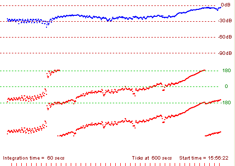
In the example on the right, the integration time is 60 seconds. The amplitude plot is in blue, and the phase plot in red. The phase plot shows
two 360� rotations in order to preserve continuity. WWVB on 60kHz appears out of the noise for about four hours in the middle of the night (this is at 10,000km range). The upward slope illustrates changes in the ionosphere causing
advancing phase by about 180�, equivalent to a Doppler shift of 30µHz. The small notches every hour are a clear indication that the signal is WWVB - it is the only
transmission on this frequency to use the phase advance signature.
It is quite practical to generate your own GPS coherent transmission. The simplest way is to use a crystal oscillator at some easy multiple of the intended frequency (for example 137.5kHz x 64 = 8.8MHz), and divide down to the operating frequency. Use the GPS 1pps signal leading edge to reset the divider every second, and if the oscillator is carefully adjusted, the divider will generate a coherent carrier with low 1Hz phase noise sidebands.
Another way is to use a Direct Digital Synthesizer (DDS) which can be phase set by the GPS 1pps event. The ZL1BPU LF Exciter has this feature, including the ability to set the transmitted phase angle.
Unfortunately it is not enough to just use a highly accurate reference (such as an Oven oscillator or even a Rubidium Standard) for the transmitter divider, as although the phase may stay fairly constant for minutes (OCXO) or hours (Rubidium), it will never be possible to predict the transmitted phase or infer anything from the received phase.

Software
The software discussed here is CLICKLOCK2 by Con ZL2AFP. This software uses the G3PLX Clicklock algorithm, and provides a series of tools allowing analysis of GPS coherent signals. The main output is a pair of graphs plotting signal level (in arbitrary dB) and signal phase, measured in degrees. These two graphs share a common timebase, so you can assess the signal phase and amplitude together, just as you would with a filter analysis tool. This information is extremely interesting, as after all, the ionospheric mechanism is not dissimilar to a filter.
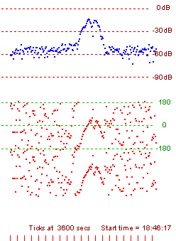
In the example to the right, the signal shown is DCF77 on 77.5kHz, received at around sunrise at a range in excess of 15,000 km, with an integration time of 360 seconds (six minutes!). The signal is 30dB out of the noise (using this technique) for about two hours. Using ARGO or similar, the signal is barely detectable, and certainly not identifiable.
- Download:
- ZL2AFP Clicklock and PDF Manual
- ZL2AFP Clicklock screenshot
Copyright © Murray Greenman and Con Wassilieff 2007.
All rights reserved.

