Hellschreiber was patented in 1929, and is still in use today, using the original format. Hellschreiber was the first successful direct printing text transmission system, and was very popular at a time when teleprinters were complex and expensive (the Hell receiving mechanism had only two moving parts). At first the Hellschreiber was mostly used for land-line press services, which continued well into the 1980s.
A military version was used by the German Condor Legion during the Spanish Civil War (1933).
During WWII, Hellschreiber was widely used for field portable military communications, for which it proved to be very suitable because the equipment was simple and robust. Today we use the term "Feld-Hell", or "Field Hell" for this system, to help differentiate it from the slightly different land-line press systems, and others of more recent invention.
How Characters are Transmitted
Each character of a Feld-Hell transmission is portrayed as a series of dots (picture elements or pixels), in a matrix, just like the printing of a dot-matrix printer. The dots are sent one at a time, rather like Morse code. Feld-Hell transmits in the following order - up each column from bottom to top, then up each following column from left to right.
There are typically 14 dot positions per column (although this varies), and five columns per character
(again this varies), followed by two blank columns between letters.
The following picture shows a fragment of text 'BCDE', depicting the order in which the dot elements are transmitted and printed. Each of the dotted rectangles represents a potential dot location, and is identified by a locating letter/number. The transmit order therefore is A1, A2, A3... A7, B1, B2... etc. In the picture
seven rows of dots are numbered. Actually this is a simplification - there are usually 14 dots per column, and are treated here as pairs, which is why they appear taller than they are wide in the diagram. In some places only one of the pair is transmitted. This is all explained further down the page.

Hell character pixel detail
In this picture, the dotted rectangles depict individual dot locations in the matrix. There are blank, untransmitted picture elements (pixels) at the top and bottom of each character, and between characters. These are depicted as empty white rectangles. The transmitted (key down) pixels are shown black. Looking at the above diagram, it is easy to see that the transmitter duty cycle is quite low (about 22%). Another way of saying this is that the peak-to-average ratio is very high, which is important for good readability in noise.
150 characters are transmitted every minute. Each character takes 400ms. Since there are 49 pixels per character (if you assume seven pixels per column), each pixel is 8.163ms long. The effective baud rate is 1/8.163 ms = 122.5 baud, and the throughput is 2.5 characters/sec, or about 25 WPM.
The Two Pixel Rule
The original Feld-Hell equipment, and the best software implementations, transmit two pixels (each half height, or half the duration) for every dot shown in the diagram, thus improving the vertical resolution.
You would expect this to increase the transmitted bandwidth.
If you look carefully at the above diagram, you can see how this improvement comes about without increasing the signal bandwidth. Rudolf Hell designed the font so that a single half-height pixel is never transmitted. For example, the right side of the "B" has enhanced resolution achieved by slipping the timing of the full-height pixels by half the height of one pixel. Three half-height pixels are transmitted without a break, so the bandwidth is not increased. Look at other characters and you should see other places where this technique occurs.
Another important reason for the restricted bandwidth design, while providing well defined characters, was that this technique ensured that pulses to the radio transmitter were never less than 8ms. Shorter (half-pixel) pulses could be severely distorted by the slow rise-time of the transmitter, and as a result, cause excessive bandwidth or poorly defined dots which would fail to energise the mechanical print hammer in the receiver.
Dot Shaping
Another important technique which limits the bandwidth of Feld-Hell transmissions is the use of carefully shaped dots, using a low pass filter (the original technique) or a raised cosine profile. If the signal is hard keyed, the 122.5 Hz keying sidebands generated will spread out for some 500 Hz either side of the carrier. Older systems achieved dot shaping using a keying filter (just as is used for Morse transmissions), but now the effect is achieved more effectively through signal processing.
The picture below shows an oscilloscope shot of the raised cosine signal from a real transmission, two pixel-pairs, and a group of pixels run together, with the shaping only at start and finish. Note the shape of the individual dots, and that each dot is identical. Without the shaping, which confines the bandwidth to about 245 Hz, the signal would be very wide.
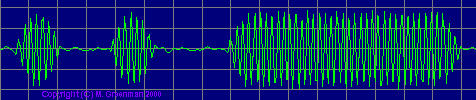
Feld-Hell keying with raised cosine envelope
The raised cosine profile effectively modulates the carrier with a 122.5 Hz sinewave during the dots, and the result is a 100% modulated carrier, i.e. with one pair of sidebands spaced 122.5 hz either side of the carrier, rather than a wider pulse modulated signal.
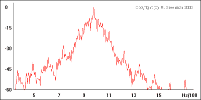
Raised Cosine Feld-Hell spectrum
This spectrum of the real Feld-Hell signal above looks rather wide, but remember that the vertical scale is logarithmic. Note that the keying sidebands drop off quickly (300Hz wide at 30dB down). Compare this with the next picture, which shows hard-keyed Feld-Hell. The difference is obvious! The strong component at around 600 Hz is typical of wider systems - the old LA0BX DOS software can be distinguished by this transmission 'feature'.

Hard keyed Feld-Hell spectrum
Many software Feld-Hell systems can also transmit each column twice, for double width characters, which give better readability under poor conditions.

Double-width characters transmitted on 181kHz
The receiving system is compatible with the two-pixel technique and this double column variation without any changes. Many other adaptations are possible while retaining receiver compatability, for example transmitting small pictures, narrow faster characters, proportionally spaced fonts, or foreign language fonts. The number of pixels per column and number of columns per character can also be altered - so long as there are exactly 17.5 columns per second, and the bandwidth is controlled, it will make no difference to the receiver.
Character Generation
In the original Feld-Hell machine, the characters were generated in an interesting way. A drum contained one ring of brass contacts for each character provided on the keyboard. When a key was pressed, the drum rotated once, and in the process, transmitted via a contact the dots required for that character. A mechanical interlock prevented keys being pressed simultaneously, and at the same time ensured that each new character started at the correct time to preserve the phase of the transmission. Using the keyboard was a challenge, because each new key needed to be pressed lightly during transmission of the previous character, to 'lock in' the character at the correct time, rather like the technique required for some Morse keyers! Otherwise a space would be transmitted between characters.
Since only one ring of dots was used per character, and the drum was rotated once per character, rather than once per column, the character matrix was rearranged in a line around the circumference of the drum. Compare the drawing below with the one above:

Drum layout on mechanical Hell transmitter
In this drawing, the pixels are labelled the same as the previous drawing, but note that each character starts at the left, and each column of pixels follows the previous column, labelled A, B, C.. etc at the bottom of the drawing. Now imagine the full character set added above and below the four characters shown, the black pixels representing the brass contacts, then wrapping the drawing around a vertical cylinder.
The output of the war-time Feld-Hell machine was a 900 Hz keyed audio tone, sent on a telephone line or to a transmitter modulator, for example an MCW transmitter. It was possible in some models to separate the keying contacts for direct keying of a CW transmitter. Feld-Hell is therefore amplitude keyed, just like Morse, as CW or MCW. Each pixel of a dot matrix character is sent in a fixed pattern as a CW dots. Where there is no black dot, nothing is sent. Feld-Hell is in reality a simple facsimile mode. The early press system, F-Hell was identical except that it ran at 245 baud (5 characters/sec). An asynchronous variant, GL-Hell, (used by land-line machines) utilised a fixed start block of pixels at the left of each character, which provided character based synchronism, but this method has no advantage to Amateurs.
An excellent article describing the traditional mechanical method of transmitting and receiving Feld-Hell appeared in Ham Radio Magazine, December 1979. An article which describes the Hell font and includes other useful information was printed in Radcomm, April 1981. The actual machine described by the late G5XB in that article was until recently in the possession of Ian G4AKD, and now resides at the Bletchley Park Museum.
For a summary of the different Hell formats, see the Hell Formats page.
Transmission Timing
Feld-Hell characters are sent as a series of dots at 122.5 pixels/sec, using a CW transmitter, or these days, by sending tones to an SSB transmitter. Black dots are represented by a CW dot (key down), and white spaces by a space as long as one dot (key up). The timing requirements are quite precise, like FAX, but Rudolf Hell developed a simple but clever technique, which involves printing the text twice, which can negate the effects of phase and small timing errors, thus avoiding the need for true synchronism.

Two lines of text are printed for each line transmitted
This example shows how the two versions of the received characters are printed one above the other, so that the bottom of one character touches the top of the one below. Because the timing is good here, and the transmitted and received equipment phase lines up well, the purpose of this is not obvious. However, it becomes obvious when there are timing differences between transmitting and receiving equipment. The following example shows extreme timing errors, but with double-printing the text is still readable.


Single-row (left)and double-row printing (right) illustrated
Feld-Hell is therefore 'quasi-synchronous'. It is important to realise that the text is printed twice, but not transmitted twice. The font was designed so that the top and bottom of the font can match to create readable text, no matter what phase relationship exists between transmitting and receiving equipment. In the next example the timing is correct, but the phase is out such that the two printed lines appear as one good line and two partial lines:

Feld-Hell received with phase error
Modern DSP techniques can considerably improve the performance of Feld-Hell transmission and reception; reducing the transmitted bandwidth, and providing impressive receive sensitivity. Most of the software used for Feld-Hell uses a very simple sound card interface. Although not originally conceived in this way, Feld-Hell can benefit substantially from the use of DSP, specifically digital filtering, detection, averaging and analog to digital conversion techniques. 'Fuzzy' presentation for human eye-brain interpretation is especially important.
To illustrate these advantages, the transmission shown below (left) was received by ZL2AKM from OH/DK4ZC (about 20,000 km), recorded on audio tape and played back to the LA0BX software, which has digital filtering, but no DSP or analog demodulation, and, like the original Feld-Hell, lacks an analogue (grey scale) display process:


Black and white (left) and grey-scale presentation (right)
In other words, this (left) system isn't truly 'Fuzzy'. With better processing, analog detection, A-D conversion and use of a grey scale display (right), the SAME snippet of audio can be made easily readable.
The received signal is the same, but the improvement in copy is obvious! This is because by presenting exactly what is received, without any decision making, the eye and brain, not the computer, are allowed to decide what dots are present, and when they are present, i.e. what dots are relevant. The eye and brain have superior powers of pattern recognition and context based interpretation that no computer can match. All recent Hell software has this capability.
Performance
Feld-Hell performs very well where the path has reasonable stability (little fading) and where the signal level is equal to the average noise or better. If grey-scale reception is used (see above), performance at low signal to noise is much better. Feld-Hell is reasonably immune to interference, but can be badly affected by on-frequency carriers or Morse.
 |
Perhaps the most annoying effect is that of timing variations due to fading. As the ionospheric path changes, the path distance can change by several thousand kilometres, resulting in a variation of dot arrival time by as much as 20 ms. The example on the left shows two successive words of a single transmission, transmitted over short and long path, achieved by an instantaneous switching of antennas between words. The path length difference, about 6000 km, is illustrated in the upward vertical movement of all the pixels in the second word by about 20 ms. |
 |
Since each column of dots occupies only 57 ms, these mis-placed dots can make the text unreadable. When the path is very unstable, for example when there are multiple paths, the signal from each path interacts differently at the receiver, and can vary from one character to the next. As a result the text can be rendered completely unreadable. In the next example on the left, observe the letters "ONG" in the word "LONG". This distortion is solely due to changes in the arrival time on a dot by dot basis. The letter "A" in "PATH" is partly missing due to a different effect - a short very deep fade in the signal, taking it well below the noise floor. These problems are typical of lower HF frequencies. |
 |
The next example is very typical of 80m during the evening - on a 300km path, there is 16ms delay between the ground wave and (weaker) sky wave signal. Just where has ZL1AF's signal been to accumulate a delay equivalent to 4800 km? |
 |
The final example shows an example of short path and long path HF reception at the same time. Look closely at the letter "R" of "TURNED". Notice that two images of the letter are shown, displaced vertically by about 10ms. This example is of OH/DK4ZC copied by VK2DSG on 20m.
|
Notice also the fading in this last example - the "H" and "M" are weak, while the "B" is strong, and the background noise remains reasonably constant. This implies that the signal was close to the noise floor, or the AGC action would have reduced the noise. In all these examples the receiving software does of course use grey-scale display.
Copyright � Murray Greenman 1997-2009.
All rights reserved. Contact the author before using any of this material.