
High voltage boost converter for tube radio
This converter is design to supply a two tube regenerative receiver from a 6v lead-acid battery. The main goals were high efficiency and simplicity. That means I want to use already made coils, not to make a transformer. Boost circuit looks the most appealing despite a few disadvantages. The circuit diagram bellow shows the converter without PWM generator:
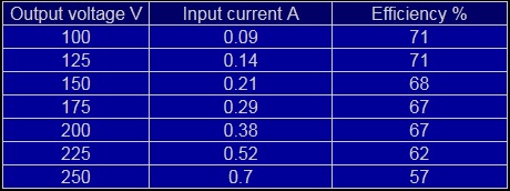
The output voltage can be adjusted between 0 to 250V (for a 26k load) by changing the duty cycle. Note that the output voltage is heavily influenced by the load. In my case this is not an issue since the tubes will be biased in class A. After trying different coils & frequency the best efficiency (around 68% for 7mA at 180V) I could get was with 1mH/1.2A coil at 2.4kHz.
The two zenner diode were added after the first transistor was destroyed when load was accidentally removed. The 47k resistor is useful during experiments in case the PWM input remains open. A floating gate mosfet can suddenly turn on just by staring at it. It's also good idea to don't use a real battery for experiments. Transistor will blow from over current faster that any fuse.You don't have to bother to find a high voltage Schottky diode to rectify the output. A regular fast type would do the job. Additional voltage drop is not an issue here. The ripple is about 400mVpp for 180V/7mA output.
Bellow is the PWM generator diagram. This circuit is a classic application of 555 circuit and it is mentioned in many places. The duty cycle is set by the potentiometer. The frequency is set by the value of potentiometer and the 88nF capacitor. In this case 250k and 88nF = 2.4kHz. The output is enough to drive two IRFP450.
This are the measured values for different output voltages (load = 26k and input voltage = 6v):
Improvements
If you plan to build a similar circuit you should consider replacing the transistors with a lower Rds type. It just happen to have a few IRFP450 but they have an Rds of 0.5ohm. An indication of how much this is was noticed when I add an additional transistor in parallel (2 in total), resulting in an efficiency increase by 20%! Also the gate threshold voltage should be small since only 6V are available to turn on the transistor. Unfortunately high drain-source voltage and low Rds requirements exclude each other but still better substitute exist at reasonable price.
Another improvement could be choosing a value for the coil that yield highest efficiency at a frequency outside audio range. My converter makes a small noise, especially at high duty cycle. As expected, the converter is more efficient if a 12V battery is used (around 15% more). This is because lower current flowing through transistors and higher voltage available to turn them on. But in my case I want to use 6v heater tubes and not to connect it in series.