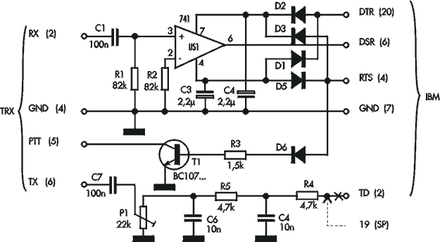
Fig. 1.
The most simple radiomodem for CW, RTTY, SSTV, AMTOR
Recently availability of
personal computers became the reason of revolution also in amateur
radiocomunication. It is enough to hear amateur ranges HF or UHF that on the
certain frequencies to hear not clear signals. These strange signals (similar to
gurgle or pozvanivanie) it only digital communication(connection) carried out by
means of a computer. Among digital ways of transfer to which concerns also CW,
are available RTTY, AMTOR, SSTV, and recently also FAX and PACKET RADIO. In this
clause(article) we would like to prove to readers, that work with digital ways
of transfer not necessarily should mean the big financial expenses.
To carry out(spend) a radio communication with
application of digital ways of transfer, the following hardware is
necessary:
- Any computer such as IBM PC 286/386/486 with komportom and
appropriate software,
- transiver HF or UHF (enough a usual radio telephone
on a range 2ě, having jack "microphone", "naushnik/dinamik" and managements -
PTT).
- The modem interfacing computer with transiverom.
Radiomodems
are made for a digital radio communication in the West by many firms. Recently
modems allowing use the big popularity to work only in mode PACKET RADIO. Modems
TNC-2 and also cheapest radiomodem Baycom/Digicom concern to this group. With
modems it is delivered sootv. The software.
Except for special (license)
programs for digital transfer, there is a plenty of programs
Shareware.
It seems to us, that would be to acquaint readers Elektroniki
Praktycznej with the description of a design of very simple and cheap modem not
bad. The most simple modem mozhna to collect from popular parts literally in
half an hour and about use popular software it will be possible to look on the
screen for example weather maps.
the RECEPTION MODULE
In a Fig. 1 the circuit of the most simple
radiomodem which can be connected to RS232 to port of computer PC XT/AT is
shown. At reception the modem receives a feed(meal) directly from jack V.24 and
does not demand an additional pressure(voltage) of a feed(meal) of operational
amplifier US1 (741, TL061...). The positive pressure(voltage) provides signal
RTS (request to send) and negative - signal DTR (data terminal ready). On
input(entrance) OU signal NCH from output(exit) NCH of the receiver or
transivera moves. The minimum level of this signal should not be less than 100
mV. The target signal with OU acts on pin DSR (data set ready).

Fig. 1.
Vsvjazi with simplicity, the whole device can
be made even without the printed-circuit-board by soldering necessary details to
contacts of socket CANON such as HD25. If this modem will be used with program
JVFAX, it is necessary to change polarity of inclusion of diodes.
The
UNIVERSAL TRANSMITTING MODULE
In a Fig. 2 the circuit some more complex(difficult) radiomodem giving an
opportunity to carry out(spend) bilaterial communication(connection) (reception
/ transfer) with use of set of programs shareware, including PCFAX, JVFAX,
EASYFAX, SSTVFAX4, PKTMON, HamComm is shown.

Fig. 2.
At reception OU executes the same role as in
the previous case. Connection of two additional diodes allows zapityvat' the
modem irrespective of potentials on lines DTR and RTS.
By transfer on
sootv. The input(entrance) transivera moves signal PTT. The positive
pressure(voltage) translates transistor T1 from line RTS (BC107...) in the sated
condition. At this time on a microphonic input(entrance) of the transmitter
signal TD (transmitted data) moves, that becomes the reason of modulation
bearing(carrying). Depending on the software, modulating signal can undertake
also with usual PC Speaker'a. In any case the digital signal with help RC of the
filter varies on sine wave, and potentiometer PT1 helps to establish on an
output(exit) the appropriate amplitude of a signal depending on sensitivity of a
microphonic input(entrance) of the transmitter.
All radiomodem can be mounted inside the plastic
case of adapter HD25/HD9 (mum - daddy) with use of the printed-circuit-board
submitted on a Fig. 3.
|
|
In a case if the modem will be
used only on reception, we do not put transistor T1 and diode D5 and also
elements RC used at transfer.
Correctly collected
radiomodem does not require adjustment, only by means of potentiometer PT1 it is
necessary to expose a target level of modulating signal.
Resistors: R1, R2 82 KOm, R3 1,5 KOm, R4, R5 4,7 KOm, PT1 22 KOm. Condensers: Ń1, C2 100nF, C3, C4 2,2 uF/16V, C5, C6 10 nF. Semiconductors: US1: ULY7741 or analogue. D1, D2, D3, D4, D5 1N4148 or analogue. T1 BC107 or another npn.
Translation of clause(article) from
magazine
" Elektronika Praktyczna
"
Dmitry
Lyoushkin
[ About me | Acronyms
| CW | Data
Sheets | Docs | Download
| E-mail | HOME
| Ham projects | Hobby
circuits | Photo galery | PIC
| QTH
photos |
Sign
in my guestbook | View
my guestbook ]
© 2001 - YO5OFH, Csaba Gajdos