MICROPHONE AMPLIFIER,
LPF AND BALANCED MODULATOR
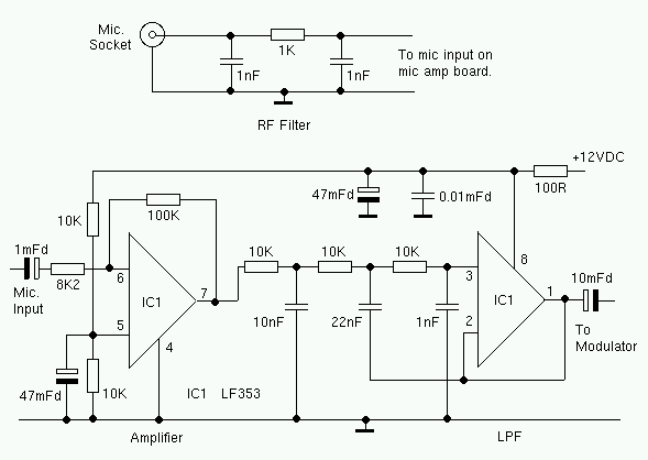
The microphone amplifier has a gain of more than 20dB. The amplifier is followed
by an 2.7KHz active low pass filter. A dual op-amp is used for both stages. The
choice of op-amp is not critical. I use an LF353 but most dual op-amps should
work in this circuit.
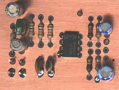
Like all the other circuit boards in this transceiver, the PCB was drawn by hand.
I used double-sided PCB. All ground connections are made to the top PCB foil (Ground
plane). The holes for any component leads that are not grounded, must be reamed
out (countersunk?) with a suitable tool. I used a 3mm HSS drill bit.
![]()
[ About me
| Acronyms | CW
| Data Sheets | Docs
| Download | E-mail
| HOME | Ham
projects | Hobby circuits
| Photo galery | PIC
| QTH
photos |
Sign
in my guestbook | View
my guestbook ]
© 2001 - YO5OFH, Csaba Gajdos