
ORIGINAL VERSION EME85A
CURRENT VERSION EME85C
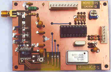
DDS Synthesizer Kit
|
|
|
|
ORIGINAL VERSION EME85A
|
CURRENT VERSION EME85C
|
The Original DDS
PC board design through to the current boards are compatable with the Original
software from the NJQRP groups Website.
This means that all Pin functions on the PIC16F84 Micro have been kept the same.
The Software allows the DDS to be used anywhere between 0 & 30MHz, &
had bandswitching to jump between the various HF Amateur bands. It also allows
the DDS to be used as a signal generator, or a local oscillator for Direct Conversion
receiver, or transmitters. The software does not allow for display offset to
DDS frequency for Intermediate Frequency type Transmitters or Receivers. The
original software although very good, was designed to use a Optical Type Rotary
Encoder for tuning. These are very expensive in Australia > $100 Aus. The
Mechanical types were tried & do work, but can cause the DDS to jump large
frequencys due to contact bounce.
Download Original
Software
Download Original PC board Artwork EME85A
( Protel )
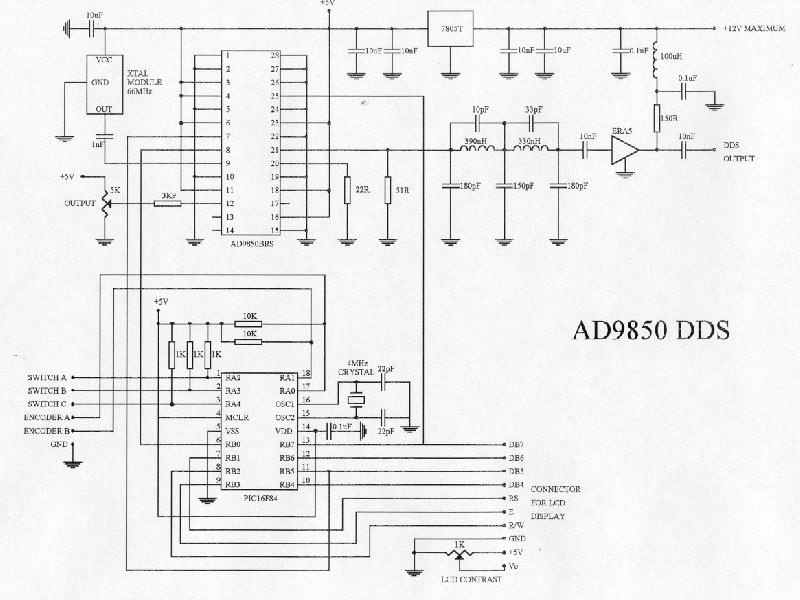
Circuit For the EME85C DDS Kit
New Software For EME85C Kit
I was looking for Software that would
allow the DDS output frequency to LCD display frequency offsets, & IF frequency
offsets to be able to be programmed to make it more useable for building equipment
for the VHF to Microwave bands. I was also looking at designing a basic SSB/CW
transceiver for 144MHz similar to a FT290R. The New Software required the following
functions.
Further Information on programming
the setup screen using the calibrate button when powering up can be read in
the Synth.ASM file. For quicker programming of the DDS software the Synth.DAT
file can be modified to suit your application.
Thanks goes to Steven Jones for Re-writing the new Software. The software includes the SYNTH.ASM, SYNTH.DAT, & SYNTH.HEX files. It is being supplied free for all Amateurs.
Version 1.10 Software has now been replaced by Version 1.30 October 2001
Download
Version 1.10 Software January 2001
Download Version 1.30 Software October 2001
The New software now allows either
a PIC16F84 or 628, or either a AD9850 or 9851 to be used. A x1 or x6 Multiplier
can also be selected when using the AD9851. There is now an option for a Repeater
offset function on TX.
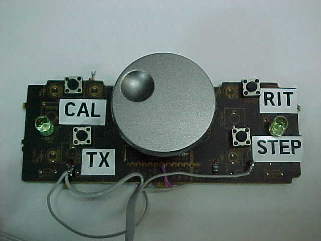
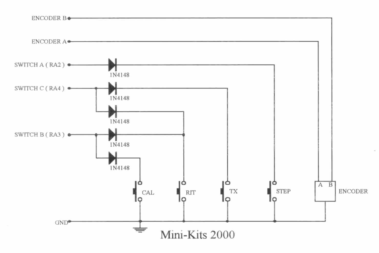
Control Board
For EME85 DDS
The control for the EME85 DDS requires a number of diodes, switches, & an ALPs EC16B-24 Rotary Encoder. The prototype is shown built on a surplus PC board from a Sony HIFI unit. The EME85C DDS board has 6 connections, Switch A/B/C, Encoder A/B, & Gnd. The Older type EME85A board will need modifying to add an extra diode to the RA4 connection on the 16F84.
 |
 |
For more Data on Pin connections for the ALPs EC16B Rotary Encoder, have a look here.
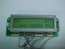
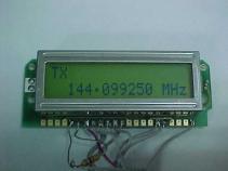
LCD display for EME85C DDS kit
Example showing the software programmed
for the 144MHz Band.
 |
 |
|
DISPLAY IN RX MODE
|
DISPLAY IN TX MODE
|
The Software for the EME85C Kit has
been written to suit Standard Hitachi HD44780 16x2 LCD displays. Displays that
either have R/W pins or not, can be used with the EME85C Software. A delay routine
as been added in the software to accomodate this. Both the LCD2 & LCD3 Displays
are compatible. The Vo ( LCD Contrast ) adjustment is not used on the LCD3 displays
as they have resistors to preset the contrast on the display.
Additional DDS notes
It is suggested that the DDS board
is mounted inside a metal box as it radiates quite a lot of spurious RF. Recently
an interference problem on channel 9 VHF was tracked down to RF radiating from
the DDS board. All leads in & out of the box should be kept as short as
possible, & use ferrites over the leads if possible.
The maximum DDS output frequency that should be used is 22MHz, which is 1/3
of the 66MHz crystal oscillator frequency. There is quite a lot of spurious
produced above 22MHz so a 20MHz low pass filter has been used to filter the
spurious & 66MHz clock frequencies from appearing on the output. For higher
output frequencies, you will have to increase the crystal frequency, & change
the low pass filter to suit.
The highest possible frequency recommended for the AD9850 is around 40MHz using a 125MHz crystal oscillator. To produce an even cleaner output, it is suggested that the DDS output is mixed with another frequency to produce a new output & then filtered. The frequency display can be offset to accommodate this.
New circuit version without rotary encoder (with optical encoder from mouse)

Optical encoder from PC mouse
Original schematics from http://www.njqrp.org/ham-pic/ and http://www.minikits.com.au/index.html. Tnx!
![]()
[ About me
| Acronyms | CW
| Data Sheets | Docs
| Download | E-mail
| HOME | Ham
projects | Hobby circuits
| Photo galery | PIC
| QTH
photos |
Sign
in my guestbook | View
my guestbook ]
© 2001 - YO5OFH, Csaba Gajdos