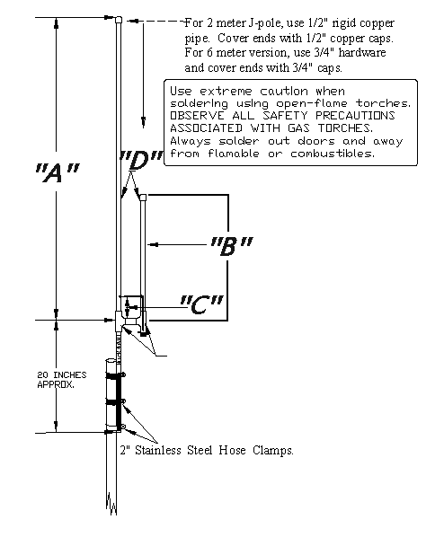
FIGURE 1a
FIGURE 1b
I've had many requests for a ready-made J-pole design that will enable the
Packet Radio user to print the image from a web page and go directly to the
construction table and build a J-Pole antenna for their Packet Radio station.

The object is to eliminate the need to go through all the calculations on
another page of this website.  These requests are valid and understood!
With your requests in mind, here are "the real world" designs that I've
personally constructed and use at many of my Packet Radio node locations.
A VARIATION ON A THEME: Let's look first at FIGURE 1a; This is the overview and profile of the J-Pole we will be working with. There are two different bands we will be building the J-Pole antennas for. NO, we will not build a two band antenna on one mast. I've been there, done that.. and it is an excercise in futility. For openers, I would like to show you that all J-poles are not created equal. By that statement I mean, we will modify our construction techniques a bit and apply a variation to the theme. Notice in the exploded view at FIGURE 1b, I've deviated from the usual RF feed technique that we normally use to attach our coaxial cable to the J-pole. Where we usually attach the shield and center conductor to the tuning stub and the driven element with aeroseal (hose) clamps, here we've made a slight change in the design by exchanging the elbow for a tee. Below the short (1/4 wave tuning stub) section, we (carefully) soldered an SO-239 (Chassi-mount) coax (female) connector. But notice that we must first attach a piece of number 10 or 12 insulated, copper wire to the SO-239. The length of this wire depends on the spacing between the stub and (Fig 1A "D") long section of our antenna. If the antenna is for six meters, the wire length will need to be about, 10 to 12 inches long. If our antenna is for two meters, the wire length will be less than 8 inches overall. I am careful when I (Benz-O-Matic torch) solder the SO-239 to the copper tee, since I don't want to heat the SO-239 to the point the solder on the wire melts and I have to start the process over again.For 2 meters (145.000 to 146.000 MHz) the EXACT dimensions are:A = 58 inches overall (Long, driven element). B = 19.5 Inches C = 2 Inches D = 1.8 Inches (space) For 6 meters (50.500 to 51.500 MHz) the EXACT dimensions are: A = 166-3/4 inches overall (long, driven element). B = 58-3/4 inches (short, tuning stub). C = 5.5 Inches D = 5 inches

FIGURE 1b

|
Ham radio Data Center - free schematics | Free HAM Directory | About me | Acronyms
| CW | Data
Sheets | Docs | Download | E-mail | HOME | Ham projects | Hobby
circuits | Photo galery | PIC | QTH
photos |
Sign
in my guestbook | View
my guestbook ]
© 2001 - YO5OFH, Csaba Gajdos