14MHz
SSB 10mW transceiver
by JF1OZL
The reason of this events: The reason of this production is very simple. I wanted
to QRV on 14MHz SSB mode. One day when I walking on Akihabara city in Tokyo
, while I have heard the sample transceiver on the ham shop ,I have known that
14MHz can be used for domestic communication. They made Japanese domestic QSO
about 14.18MHz.
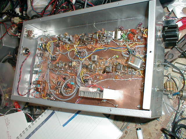
The whole Construction : You can call the transceiver like this as "OZL
type". Characteristics of the "OZL type" are as follows.
1. Single conversion super.
2. Using two DBM-s as modulator and converter.
3. Modulator DBM is used as demodulator in receiving time.
4. All amplifiers are used in transmitting and receiving time.
5. Case is second use of my failed or useless machine.(This time I used my useless
old 10W 7MHz transmitter.)
6. All decals are done with the "Magic ink". Very simple way!
7. Normal "OZL type" uses 12V DC power from cigar lighter of the car.
But in this machine I used 20V DC from my DC power supply. The reason of my
choosing high voltage are as follows. One reason is in order to press the variable
capacitor of the VXO oscillator for it's minimum capacitance and to get the
highest frequency and to get the wide frequency range of the operation. Second
reason is to use 24V relays instead of 12V relays. I got these 24V relay with
only 10 dollar for 10 peace. It was cheep Junk but super micro molded type can
be used for 430MHz. The name of these relays are G6H2-24V. Maker is OMRON company.
Third reason of high voltage is in order to get 10W power easy with good linearity.
In my experience it is difficult to get 10W with 12V power pupply.
Explanation of the circuit diagram:
1. The black circle marked capacitor is 0.01 micro F ceramic capacitor.
2.You should adjust the snow marked two capacitors on the oscillators to be
got the maximum each output power.
3. All NPN transistors who has no mark are 2SC1815. Maker: Toshiba. Usage :signal
amplifier. Pc=0.4W, Vcbo=60V, Hfe=70 to 700, ft=80MHz.. I show you the character
of another transistors as follows. 2SC1815:maker=Toshiba:usage=amp:Pc=0.4W:Vcbo=60V:Hfe=70to700:ft=80MHzmin///
2SC1740:maker=Rohm:usage=universalamplifier:Pc=0.3W:Vcbo=50V:Hfe=120to820:ft=180MHz///
2SC2491:maker=Sanken:usage=powersalamplifier,switching:Pc=50W:Vcbo=100V:Hfe=unknown:ft=30MHz///
2SC1969:maker=Toshiba:usage=CB bandRFpoweramplifier:Pc=20W:Vcbo=60V:Hfe=unknown:ft=unknown,
(Po=18W,at27MHz,Vcc=12V,Pi=1W)
4. FET used on carrier oscillator is 2SK241. Maker Toshiba. Mos FET. Usage =FM
VHF amplifier. Id=30mA, Pc=200mW, Idss=1.5 to 14mA, gm=10mS, Crs=0.035pF, PG=28dB
on 100MHz.
5. FIve micro relays named "G6H2-24V" are used as switching the connection
of the circuit, from receiving to transmit. This relay is made by Omuron Co,.
in Japan.
6. T1,T2,T4 are FB801 tri -filer 2turn with 0.2mm diameter enamel wire.
7. T3 and T5 are FB801 deca-filer 2 turn. Deca filer means the transformer made
with four wires.
8. T6 is FB801 double filer 2 turn. Double filer means the transformer made
with two wires.
9. Low pass filter are made with the coils "8.0mm diameter bobbin, 0.2mm
EW 7 turn." This is designed as a Pie type low path filter with Q=1 frequency
is 14MHz.
Block diagram of trnsmitter
signal flows left to right
| dinamic microphone |
audio amp |
DBM1 as modulator |
11.806Mhz DSB signal |
crystal filter makes it to LSB |
IF AMP |
DBM2 as convertor |
14MHz USB |
14MHz BPF |
3stage HF AMP |
LPF | ANT 14MHz USB 10W |
| upper | 26MHz go upper |
||||||||||
| carrier oscillater 11.806MHz |
buffer AMP | 2channel VXO 13MHz |
pusu-pusu doubler |
Signal flow on transmitting time:
1. I use 600 ohms dynamic microphone. It generates 50mVc-p signal with my voice.
This audio A- class amplifier has 30dB voltage gain. Therefore my voice becomes
over1Vc-p signal on it's outside. LED diode clipper is used to limit the amplitude
of the outside of the audio amplifier for 250mVc-p. LED 's inner impedance become
low when its voltage becomes over 2 volts. Four LED's are connected parallel
series. Therefore the amplitude of the first side of the audio output transformer
cannot be 4Vp-p. This audio signal is used to modulate the carrier in the next
stage.
2. Carrier oscillator is constructed with 11.806 named crystal and FET. It oscillates
11.8072MHz actually. In order to generate the frequency on the upper slope of
the crystal filter , this oscillator shall be tuned at this frequency. In this
case I had to use FET only on this circuit. With transistor I could not tune
the frequency on 11.8072MHz. When I made D-G pierce oscillator the frequency
became higher than 11.808MHz. I changed the oscillator circuit to G-S pierce
circuit. Then it oscillated 11.805 MHz. I changed the two crystals parallel
, the frequency became 11.806MHz. I got 11.8072MHz by connecting three crystals
parallel. In order to drive the double balanced modulator (DBM) as it's requiring
local port signal strength , that is over 1mW, I had to set the buffer amplifier
between the local oscillator and LO port of the DBM. This buffer outputs 2Vc-p
signal. It is enough strength to drive the four diodes of the DBM and not to
be disturbed by the audio signal on RF port of DBM. LO port carrier signal have
to be strong more than 10dB than the modulating signal of RF port, to ensure
the correct action of the modulator. Or else , the modulated signal becomes
" over modulation".
3.Please look another page of my home page about the construction and action
of DBM. Here I used four silicon signal diodes named 1S1588(Toshiba Co,.). And
also I used a pair of ferrite core named FB801, to construct each double balanced
mixers. Here this DBM1 is used as a modulator. Here the 11.8072MHz CW signal
is modulated by the audio signal. On the IF port of this DBM1 happens (comes
up) the carrier suppressed double side band signal. You can see the 56 ohm resister
on the IF port of the DBM1. It is used to shorten the output impedance of this
DBM, not to be over 56 ohms. Without this resistor , the carrier suppression
become 20dB worse. With this resister the carrier suppression are achieved as
about -40dB.
4. Because the carrier frequency is located on the upper slope of the pass band
of the crystal filter, only lower side band of the double side band signal on
the IF port of the DBM1 can be pass through crystal filter. Upper side band
signal is rejected to path through the crystal filter.
5. This lower side band signal (LSB) is amplified with the IF amplifier. The
LSB signal came out of this amplifier is 400mVc-p with 50 ohms load.
6. In order to get the wanted 14Mhz USB signal from this 11.8MHz LSB signal,
26MHz CW signal shall be used. The calculation is " 26MhzCW -11.8MHz LSB=14.2MHzUSB".
Please remember that "when the mixer generates the difference of two input
signals, the USB changes LSB, LSB changes USB", and, " when the mixer
generates the sum of the two input signals , USB became from USB, LSB became
from LSB". I have about 5 kg of crystal ( several hundred). I chose from
this stock the crystal named 13.025MHz. With this crystal VXO ( crystal controlled
frequency tunable oscillator) is constructed. It generates from 13.0119 to 13.0257
MHz. This signal is doubled with a push - push doubler. The output of this buffer
amplifier is from 26.023 to 26.0514MHz1.5Vc-p CW signal with 50 ohms load. This
signal drives the LO port of the DBM2.With This local signal I can make 14.2166
to 14.2442MHz as it's transmitting frequency. Yes It can be used on the SSB
band. But I want to make about 14.18MHz in order to get many chance to meet
the Japanese domestic stations. Therefore I requested to ham shop to send me
13.000MHz crystal. With using this crystal, I could oscillate 12.9975 to 13.0043MHz.
I can QRV from 14.1878MHz to 14.2014MHz with this crystal as indicated channel
one on the circuit diagram.
7. On the DBM2 , 26MHz CW and 11.8MHz LSB signal is mixed. And the 14.2MHz USB
signal is obtained(got) on the RF port of the DBM2. Here the signal rebels of
the local port and IF port shall be compared. Anytime the LO port shall be driven
stronger then IF port more than 10dB.
8. Already I got 14.2MHz USB signal. This signal is amplified by the Radio frequency
(RF) amplifier unit. The first step of the RF amplifier is made of A class single
amplifier. The second step of the RF amplifier is constructed by the B- class
push- pull amplifier. In order to stabilize the bias of final amplifier the
power diode 10D1 is used with a 30mA of bias current. Here shall not to be used
the small signal silicon diode like 1S1588. Please remember that " With
more current on the bias diode, more stable of the bias circuit is achieved".
T3 is made from four wire transformer. Instead of T3, two tri- filer transformers
can be used. But T3 is more save resources type. ( But to make such a hand made
rig with myself is not "save resources type action" as itself. Anyway
the amateur radio is the "King's hobby", effective only to spend money
and time)....On the front of the RF AMP unit , the 14MHz band pass filter is
located. This filter reject to income some unwanted signals coming to RF AMP
unit. On the end of the RF AMP unit, 14MHz low pass filter is located. It prevents
to go out the unwanted harmonized signal born in RF AMP unit. Without this filter
, this rig may cause the TVI , we call "I- chen" in Japanese. This
filter is required by the government to allow to use the rig as a machine of
amateur radio.
Block diagram of receiver
signal fows left to right
| ANT 14MHZ USB |
14MHz BPF |
2stage HF amp |
DBM2 as convertor |
11.806Mhz DSB signal |
crystal | IF AMP |
DBM1 as de- modulator |
pri AMP |
AF AMP |
head phone |
| 26MHz go uppe |
upper | |||||||||
| 2channel VXO |
13MHzpusu-pusu doubler |
carrier oscillater 11.806MHz |
buffer AMP |
Signal flow of the receiving time:
1. The 14MHz USB signal came from the antenna (aerial) is amplified by the RF
amplifier unit.
2. This 14MHz USB signal and the oscillated 26MHz signal are mixed on DBM2.
It products the 11.8MHz LSB signal. We call such a character of DBM to send
a signal from RF port to IF port and from IF port to RF port as "two way
ability". I feel this ward may be English or German originally. My translation
made from Japanese with my sense. I am afraid to make miss translation.
3. This 11.807MHz signal is amplified by the IF amplifier. You can see the collector
current is reduced when receiving time. Instead of this method the IF amplifier
makes unwanted self oscillation.
4. Also in this receiving time, 11.8072MHZ carrier drives the LO port of the
DBM1. Therefore the carrier suppressed upper side band signal (USB) on the IF
port of the DBM get the carrier again. It becomes the audio signal on the IF
port of the DBM1. This process is called as the demodulation.
5. This demodulated audio signal is amplified by the audio amplifier. And it
is heard with the head phone. In receiving time pri-audio amplifier is add to
audio power amplifier to get more total gain. And the audio is heard with head
phone.
The result of this transceiver:
I made nine QSOs with this rig and 14MHZ dipole antenna on the berranda of my
house about 10M high. Please look the end of this page ! I made contact with
another aria in Japan from my house located in Tsuchiura city. 14MHz can be
used only from 10 o'clock before noon to two o'clock after noon for domestic
communication. But I feel I would have Yagi antenna!!
Original documentation and schematic: http://www.intio.or.jp/jf10zl/index.html
![]()
[ About me
| Acronyms | CW
| Data Sheets | Docs
| Download | E-mail
| HOME | Ham
projects | Hobby circuits
| Photo galery | PIC
| QTH
photos |
Sign
in my guestbook | View
my guestbook ]
© 2001 - YO5OFH, Csaba Gajdos