Universal frequency meter |
|
This is 7-digit frequency meter measuring frequency from 10 Hz up to
1300 MHz. It is based on ideas of PIC16F84 based frequency meter.
Hardware is very simple:
It contains:
Note: "Calculator display" means (say) 7 digit LED multiplexed display. Common cathode display is used. Software is written for common cathode. For common anode displays it requires some software and hardware modification . PIC is used as 3 byte counter. If it counts 0.1 s maximum measured frequency is FF FF FF, e. g. 167.77215 MHz (theoretically) - practically 25 - 30 MHz. SAB6456 is used as 1:256 predivider. Its upper limit is 1300MHz. The device uses internal prescaler of PIC as low byte of counter, TMR0
as middle byte and some register as high byte of counter. The software
DOESN'T read anything from any input port. RA4 is used as prescaler
input.
Measuring period is 100 000 us (HF) or 256 000 us (VHF and UHF). The main steps during measuring period:
Total timing formula: For low frequency N = Fx * 100 000/4
The values for T,T1,T2,T3 and Z you can easily find using my program. To calculate values for low frequency use ledxt123.exe, for VHF/UHF use ledxt123.exe program. You can get source code. Some ideas were taken from "Simple low-cost digital frequency meter using a PIC 16C54" (frqmeter.asm) written by James Hutchby, MadLab Ltd. 1996.
This software is free for private usage. It was created for HAM radio community members. Commercial exploatation is allowed only with permission of authors.
Frequency meter schematics:
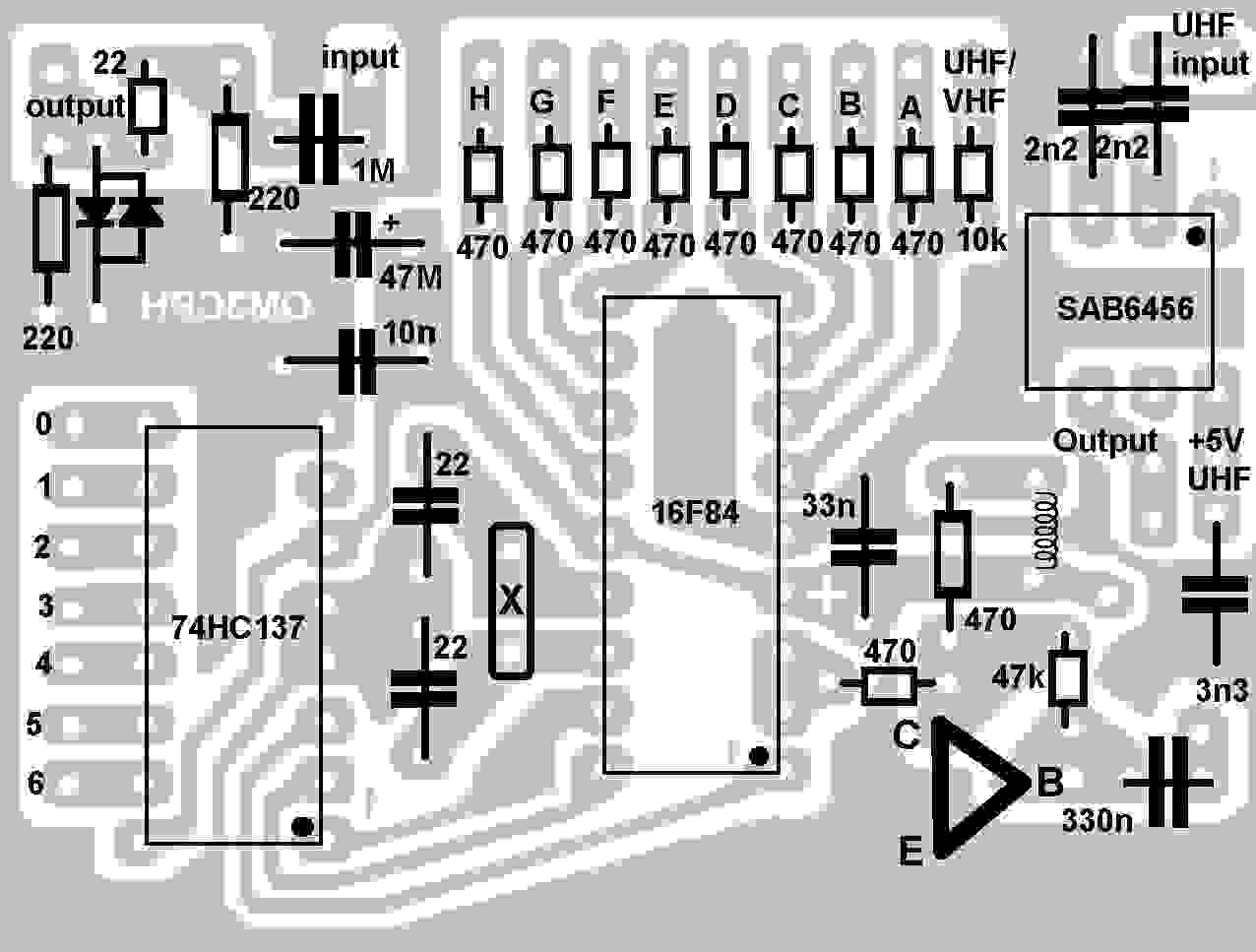
Frequency meter PCB: (54x41 mm)
Components placement:
[ About
me | Acronyms |
CW | Data
Sheets | Docs |
Download | E-mail
| HOME | Ham
projects | Hobby
circuits | Photo galery
| PIC | QTH
photos | © 2001 - YO5OFH, Csaba Gajdos |