2xGU74 Power Amplifier for 144MHZ |

Description of 2xGU74
EME operation needs high Tx power. My first EME qso was completed with only 150W and 2x DK7ZB - 3wl Yagi. Below i will present my linear power amplifier with two tetrodes GU74 in parallel configuration. Some features: high gain (18-19.5dB), stable operation without neutralization, full automated and protected.
During first test, 1.6KW output was measured at 2400V/1.2A/key down. Necessary input signal was 18W (gain 19.5dB). The current goes up to 1.4A (peak) in SSB mode. Total idle current for AB1 class operation was adjusted at 200mA (Ug1=-60V; Ug2=340V). For linear operation is recommended class AB1. In this situation grid current is 0mA and distortions caused by grid current loading are absent.
Typical efficiency of AB1 class is around 50...55%.
Maximum safe input power
Pin = 100 * Pd / 100 - Np
Pin = DC input power [W]
Pd = Plate dissipation [W]; according tube's datasheet. Tube is cooled enough to realize its maximum Pd rating.
Np = Efficiency [example: 50% = 50]; depending by class operation
For one tube GU74 in class AB1:
Pin = 100*600/100-55
Pin = 1335 Watts DC (aprox)
Pin for 2 x GU74 = 2670 Watts DC
Maximum plate current at specific plate voltage
Ip = Pin / Vp
Ip = plate (anode) current [A]
Pin = maximum input power DC [W]
Vp = plate (anode) voltage [V]
For one tube GU74:
Ip = 1335 / 2400
Ip = 0.56A (aprox)
Ip for 2 x GU74 = 1.1A...1.2A
Optimum tube load resistance
R = Vp / Ip * K
R = equivalent load resistance [ohms]
Vp = plate (anode) voltage [V]
Ip = plate (anode) current [A]
K = constant of RMS current to DC current ratio appropiate for each operation class.
K values: class A = 1.3; class AB = 1.5...1.7; class B = 1.57...1.8; class C = 2.
For 2 x GU74 in class AB and 2400V dc power supply:
R = 2400 /1.2 * 1.6
R = 1250 ohms
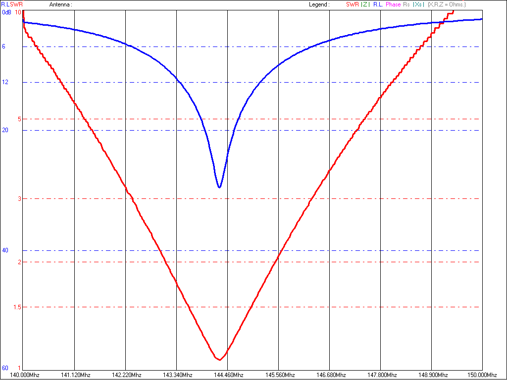
During cold adjustment of QRO, tubes impedance can be simulated using 1K...1K2 carbon resistor connected between anode line and ground. Example of anode resonator cold adjustment using VNA.
Key down 1.5KW is a realistic power if you expect a long life of tubes. Output power >2KW can be obtained using more drive signal, different class operation or higher anode power supply voltage. Take care regarding Pd recommended by datasheet, important parameter in case of digital modulation (JT65, FSK441). For CW and FM is possible to use C class operation - high efficiency (Ug1= -100V, Ug2 = 300V values tested by me). In this situation G1 current will be higher and power dissipation of grid must to not exceed 2 Watts. Class C wasn't tested due low power exciter.
Good tube ventilation is mandatory. I use airflow switch to interlock the operation and QRO shutdown. Cooling down timer delay of blower is a good practice after amplifier usage.
Mechanical dimensions and design are based on LZ1US project, similar with "144MHz high power amplifier 2 x 3CX800A ON5FF" (Dubus 3/1985).
Resonated output circuit is a Lambda/4 anodic line and sandwich PTFE capacitor. Equivalent capacitance is about 1.85nF using 0.6mm PTFE dielectric (2 x 0.3mm PTFE sheets for each side).
The original LOAD flapper capacitor was connected to ground for better coupling. In this way, the new output circuit is inductive coupled. See photos for more evidence.
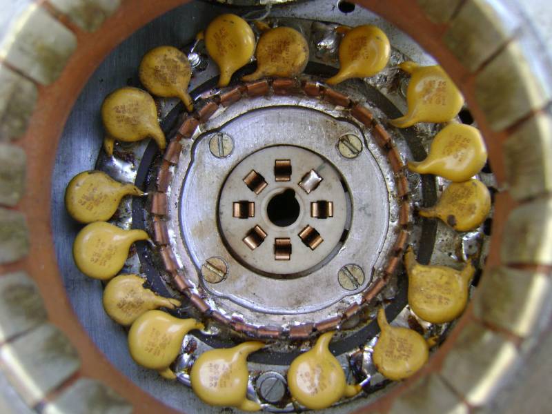
Low loss input circuit and very short connection of cathode terminals are necessary to obtain high gain. Also decoupling of screen grid is very important. I used SK-1A socket with internal capacitor. Home made socket is another excellent solution for VHF.
In cold condition and adjusted for maximum peak, the amplifier reveals more than 35dB isolation in/out, enough room to avoid any instability and neutralization.
![]()
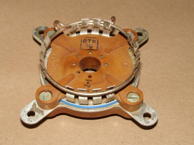
Photos of GU74 cavity
![]() Input circuit
Input circuit
![]() Cathode ground connection
Cathode ground connection
![]() Anode finger contacts
Anode finger contacts
![]() Detail of finger contacts
Detail of finger contacts
![]() Inside 1
Inside 1
![]() Inside 2
Inside 2
![]() Inside wide view during tuning adjustments
Inside wide view during tuning adjustments
![]() HV divider 18Mohms resistors
HV divider 18Mohms resistors
![]() HV divider box
HV divider box
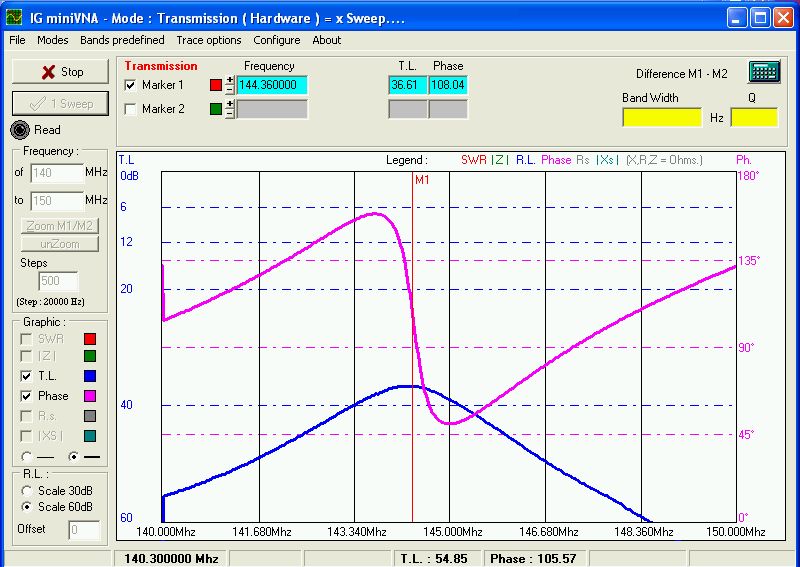
![]() VNA connected for IN/OUT coupling measure
VNA connected for IN/OUT coupling measure
![]() VNA value of grid-anode coupling (cold test)
VNA value of grid-anode coupling (cold test)
![]() Anode PTFE chimney
Anode PTFE chimney
![]() M3 screws for good ground connection and shield
M3 screws for good ground connection and shield
![]() Eccentric cam PTFE
Eccentric cam PTFE
![]() Tuning flapper capacitor
Tuning flapper capacitor
![]() Output coupling line ( last version)
Output coupling line ( last version)
![]() Ringo Ranger antenna overheated at 1KW
Ringo Ranger antenna overheated at 1KW
Update 2018
![]() G2 Board
G2 Board
![]() G2 Resistors
G2 Resistors
![]() Heatsink G2
Heatsink G2
![]() G1 Board
G1 Board
![]() Heater Board
Heater Board
![]() Heater Heatsink
Heater Heatsink
![]() QRO inside view
QRO inside view
![]() Air Flow Optical Switch
Air Flow Optical Switch
![]() QRO ready to operate
QRO ready to operate
![]() Rear Panel
Rear Panel
Automation and protection boards
![]() Controller Board YO4HFU revison 2018
Controller Board YO4HFU revison 2018
![]() Dual G2 Stabilised Power Supply revision 2016
Dual G2 Stabilised Power Supply revision 2016
![]() Heater PSU 12,6V/8A schematic revision 2017
Heater PSU 12,6V/8A schematic revision 2017
![]() Inrush protection due foldback loop (20 seconds)
Inrush protection due foldback loop (20 seconds)
![]() PCB Heater Supply (.rar)
PCB Heater Supply (.rar)
Universal High Voltage Power Supply (1600...2500V/ >1A)
Requirements:
-32A Circuit Breaker
-ON-OFF Switch with big relay controlled by simple Latch circuit. Is a good protection in case of 220V drop.
-High Power Line Filter + surge protection.
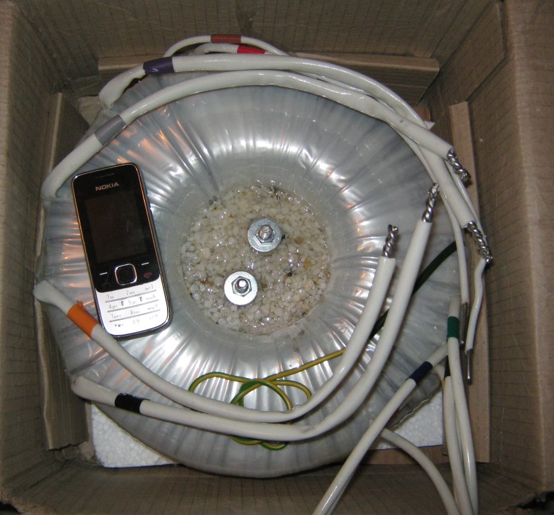
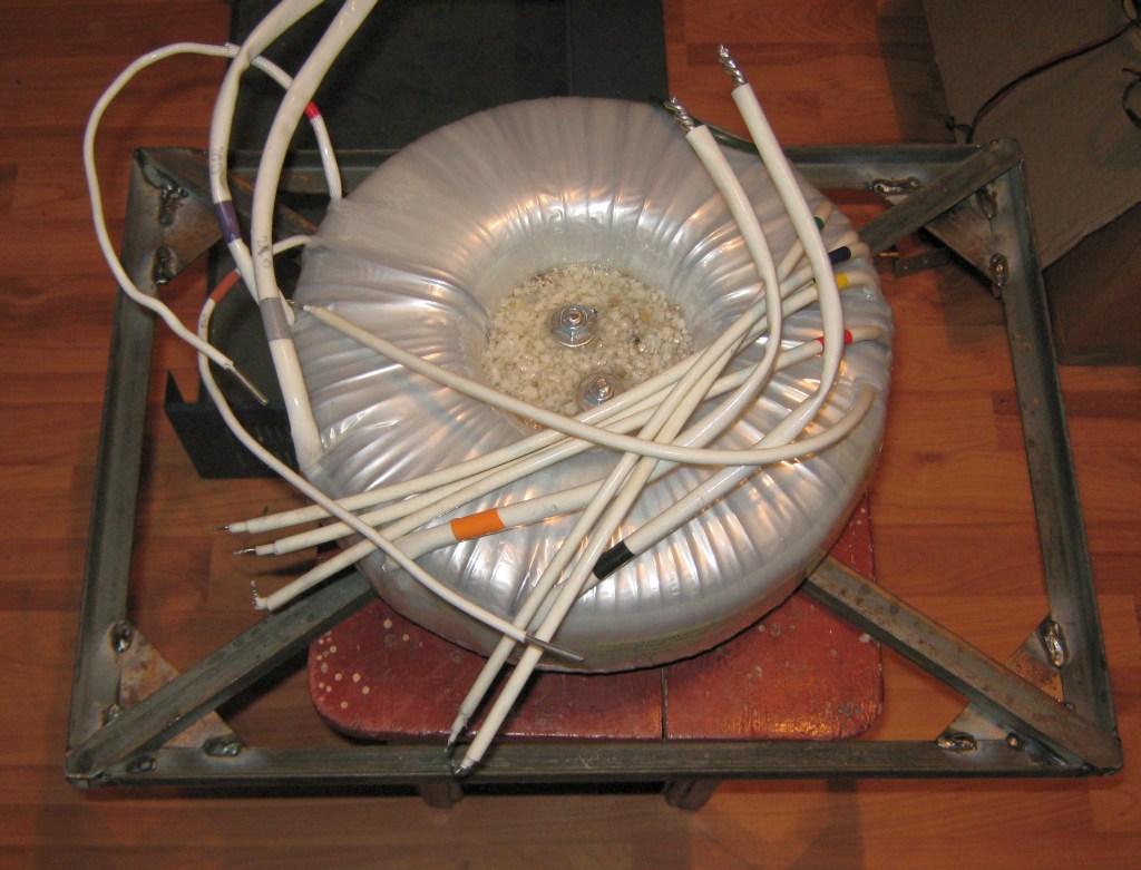
-Toroidal Transformer 4KVA(3,5KVA for continuous running). Need soft start circuit.
Weight ~ 28Kg >Foto< , Power loss: 10W. >Chassis Foto<
Primary: 200, 210, 220, 230, 240 Volts
Secondary:

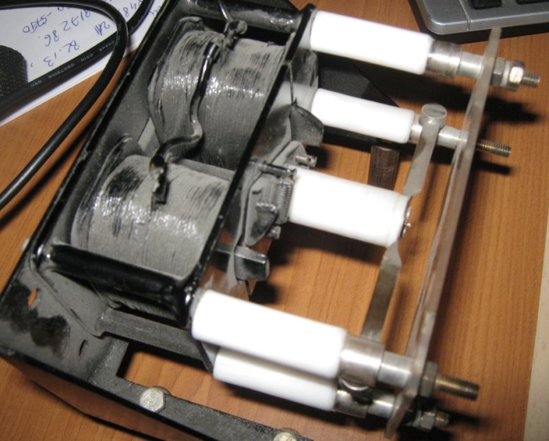
-Rectifier Bridge: 16 diodes 50R2S (1000V/6A controlled avalanche rectifiers diode), 32 x 680K resistors.
-Capacitor: 32 x 220uF/450V + 16 resistors 33K/5W for voltages equalization. Final capacity: 50 or 100uF/3,6KV.
-Bleed Resistor: 90K/180W (36 x 10K/5W).
-Limiter Resistor (glitch) 51 ohms/80W wire wound. 2A fuse for Anode circuit.
-High Voltage Relay - 220V coil >Foto<
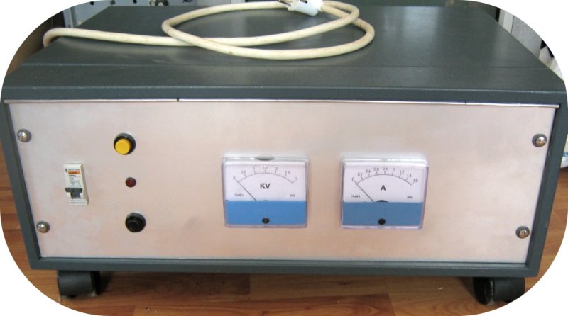
-Voltage & Current Meters
All components are oversized for reliable operation.
![]()
![]() Power supply at the begin (06.05.2013)
Power supply at the begin (06.05.2013)
![]() Front View PSU (26.06.2013)
Front View PSU (26.06.2013)
![]() Inside View PSU (26.06.2013)
Inside View PSU (26.06.2013)
![]() HV Power Supply schematic (29.01.2018)
HV Power Supply schematic (29.01.2018)
![]() Safety HV PSU - RGSB january 2009
Safety HV PSU - RGSB january 2009
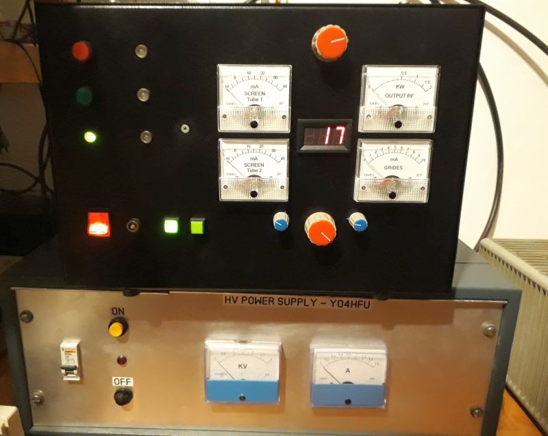
![]() HV PSU and GU74 QRO
HV PSU and GU74 QRO