LMX2330/1/2 CONTROLLED BY ARDUINO |
LMX series are single/dual PLL chips, useful devices for radio applications. The biggest obstacle is their control (programming). Typically, sequence control is achieved using "3 wires" serial communication. Internal registers are configured one by one. Register length depends on the type of PLL device: LMX2324-18bits; LMX2330-22bits; LMX2434-24bits.
LMX series from National Semiconductor is similar to ADF series from Analog Devices.
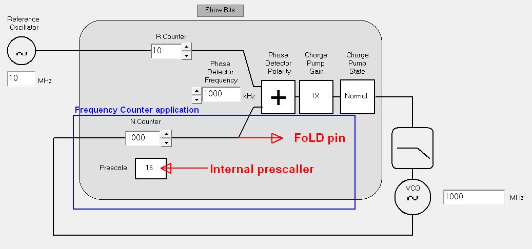
Some LMX PLL chips have a unique advantage, the internal prescaler/counter can be externally accessed. Cheap solution for any HF frequency counter extension to GHz range. Other feature is flexible divider ratio: 100/1000/10000... or even 5231...hi!
You need two PLL oscillators? No problem for LMX dual PLL chips. What could be more wonderful?
Arduino controller would do a good job with LMX, simple programming, cheap solution. Few years ago i made some tests using PIC16F628, working but i prefer Arduino solution. Check my website for old LMX-PIC projects.
Arduino Board
Any Arduino model. Check pinout allocation.
Tests made using Arduino UNO but I prefer home made LilyPad Arduino (very simple, Atmega328, internal 8MHz oscillator).
Check SI5351 project for more details about LilyPad bootloader procedure, only if you need a home made Arduino.
Arduino Sketch
This project started from G8AJN, Arduino ADF4360 PLL. ADF4360 has 3 registers x 24 bits. Hmm, LMX modifications are possible...
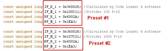
Registers values calculated by Code Loader 4 tool from National Semiconductor. Read LMX2330 Code Loader to know more about LoFD pin.
Below I choose to use 510MHz input connected to IF PLL , IF_N counter to FoLD pin, divider ratio 1000, P=16.
Remember, both PLLs can’t be accessed simultaneously.

Arduino UNO connected directly to LMX233X board (5V power supply).
The pin assignments can be changed.
******************************************************
ARDUINO pins:
Switch = Pin 8
PLL LE = Pin 9
PLL DATA = Pin 10
PLL CLK = Pin 11
LED = pin 13
Switch connected between pin 8 and GND. Is used to change divider ratio 100 or 1000, mode confirmed by LED.
*******************************************************
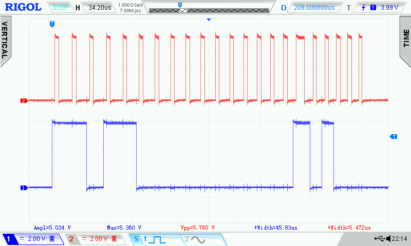
Serial signal generated by Arduino:
Red = CLOCK; Blue = DATA

IF_R register, easy to see 0 and 1 value during clock pulse.
Word: 1 1 0 1 1 0 0 0 0 0 0 0 0 0 0 0 1 0 1 0 0 0. Clock duration is 5 usec. Datasheet specification: minimum 50 nsec.
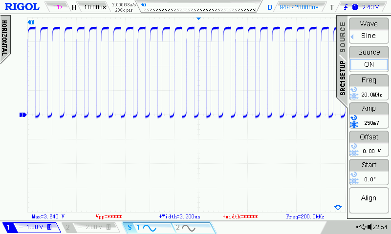
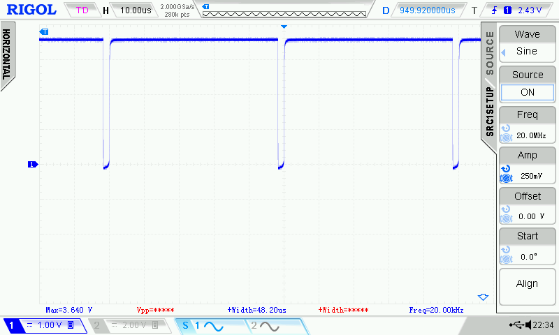
Pin (10) LoFD Output Signal buffered using a NPN transistor.
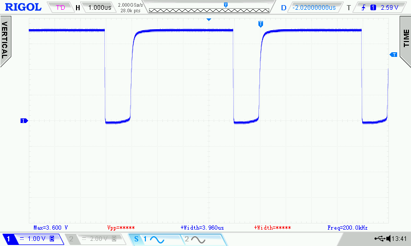
Switch OPEN, LED OFF, first preset register selected, divider 100. Input 20MHz and Output 0,2MHz.
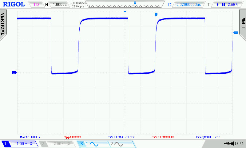
Switch CLOSED to ground, LED ON, second preset register selected, divider 1000. Input 20MHz and Output 0,02MHz.
Note: for frequency counter prescaler application, i recommend to use the highest internal prescaler. Better duty cycle was observed.
Example IF PLL: Divider with 100, internal prescaler = 8 or Divider with 100, internal prescaler = 16.
For RF PLL i didn't made measurements because don't operate at 20MHz, sine signal generated by Rigol DS2072A.
LMX233x don't accept low divider ratio for IF/RF N counter due internal prescaler.
User configuration of Arduino Code
1. Open Code Loader 4 tool. Select LMX device used for frequency counter prescaler or usually PLL oscillator.
Do not forget about FoLD selection to IF_N (510MHz) or RF_N (GHz range) if you need to use the LMX like frequency counter prescaler.
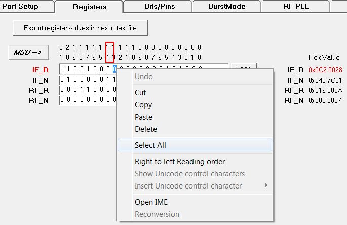
Go to Registers window, right click Select All binary bits and after Copy. MSB button must to be selected. Use a Binary to Hexadecimal Converter. Do not use Hex values from Code Loader 4!
Example: IF_R register: 1 1 0 0 1 0 0 0 0 0 0 0 0 0 0 0 1 0 1 0 0 0; Hexadecimal = 320028; Arduino value will be 0x320028.
Wrong Hex exported by Code Loader = 0xC20028.
2. Open LMX Arduino Sketch using Arduino IDE. Choose the version with external switch if you need two presets. Close the switch and restart the board, second preset configuration will be selected.
No loop used, serial data is sent only one time, better jitter stability was observed.
Uncomment state "while(true)" and " }" for loop operation. Loop operation means that the serial data will be refreshed forever when the switch is closed.
Replace Hex values calculated above.
3. Upload the Sketch. LMX Board is ready to use.
Number of registers can be easy modified. Also the 22 bits length can be changed.
Example: "bp=18" for 18 bits suitable for LMX2324.
Please, let me know if you have improvments of Arduino sketch.
PLL Low pass filter can be simulated using ADIsimPLL. For LMX2330 PLL design, ADF4217 can be selected. Check this document about ADF/LMX cross reference.

 LMX Arduino Sketch basic
LMX Arduino Sketch with switch used to select 2 presets
Code Loader 4 tool
About Code Loader configuration
ADIsimPLL 3.41
yo4hfu@2010-2021