
144 MHz - GU74b (single tube) 800W PA
Tnx to UT5JCW Serge for GU74b tube as present
Project based on JH2CLV design
http://www5a.biglobe.ne.jp/jh2clv/handmaderadio.htm
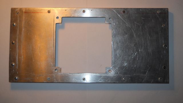
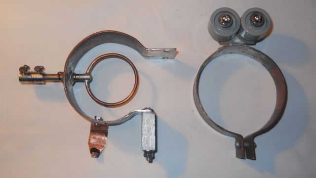
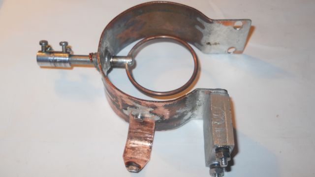
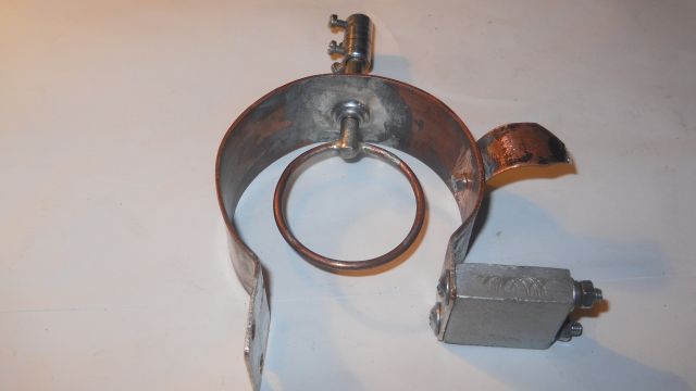
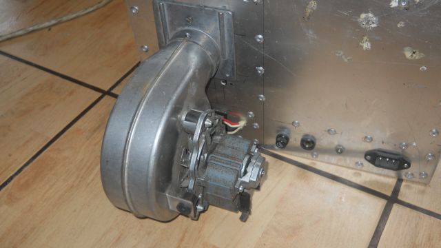
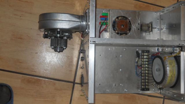
Metal work
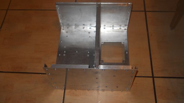
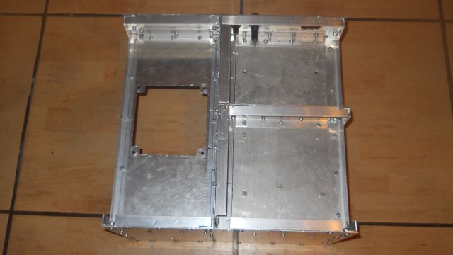
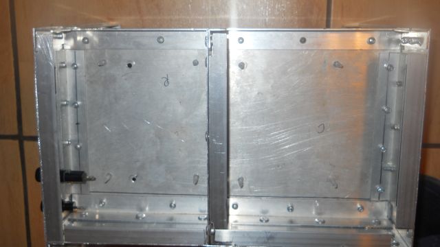
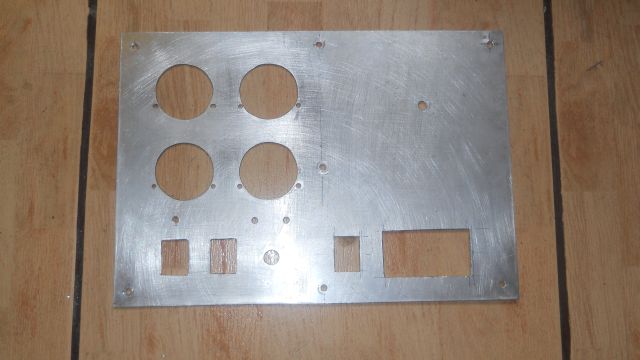
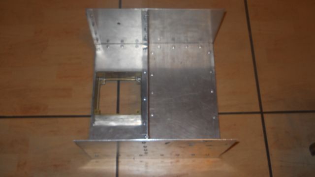
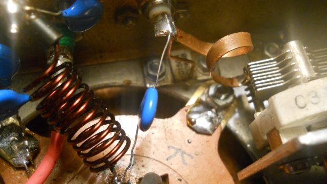
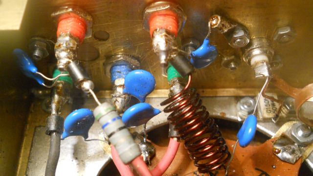
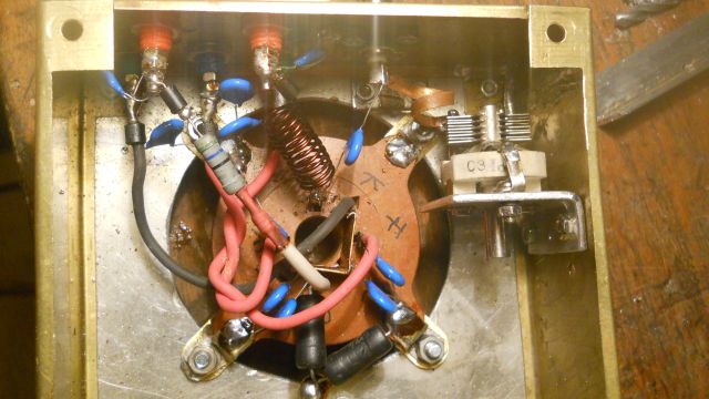
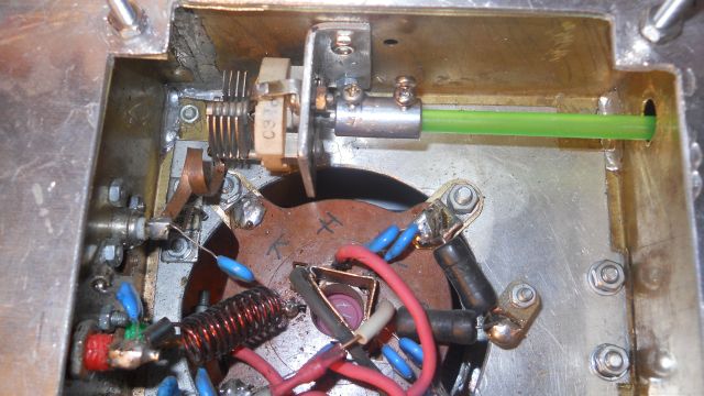
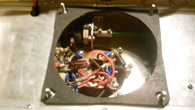
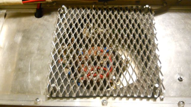
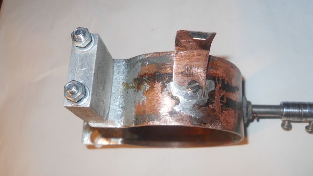
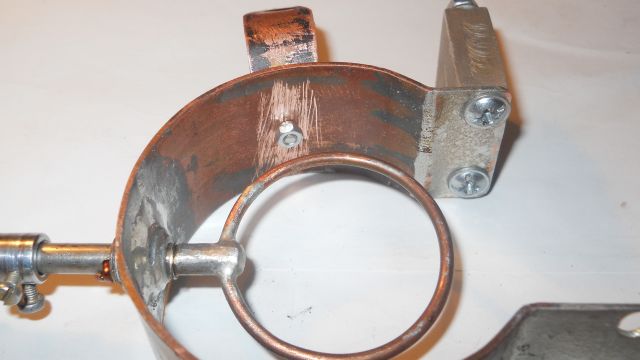
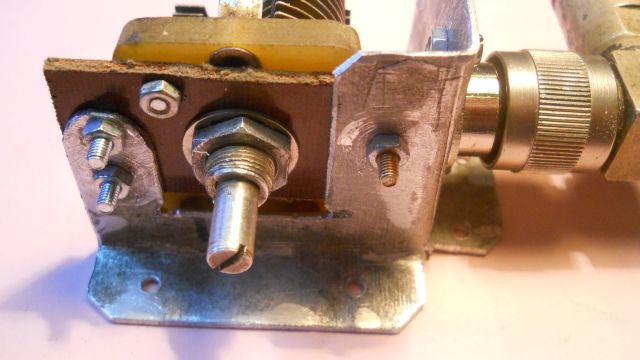
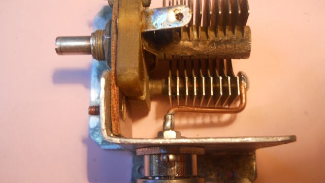
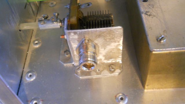
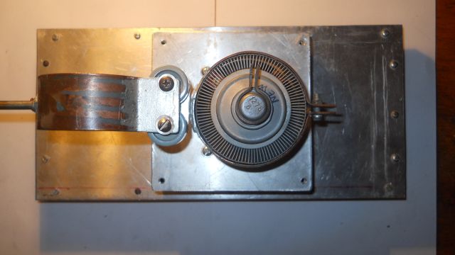
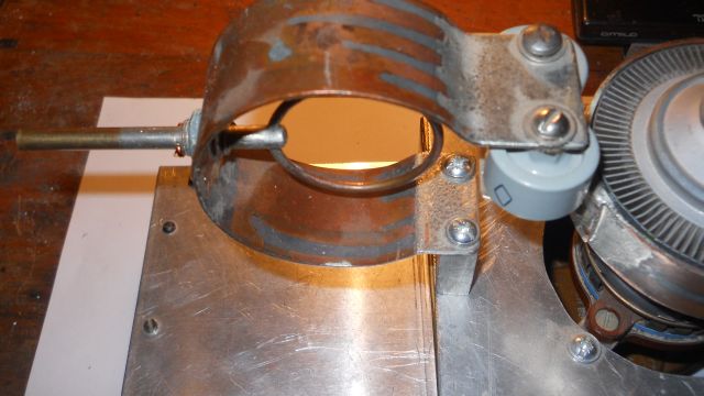
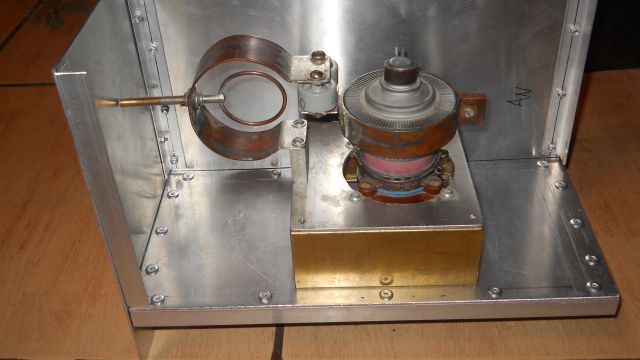
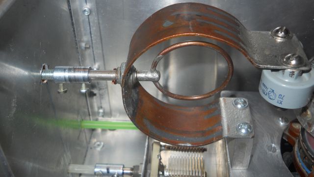
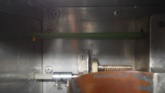
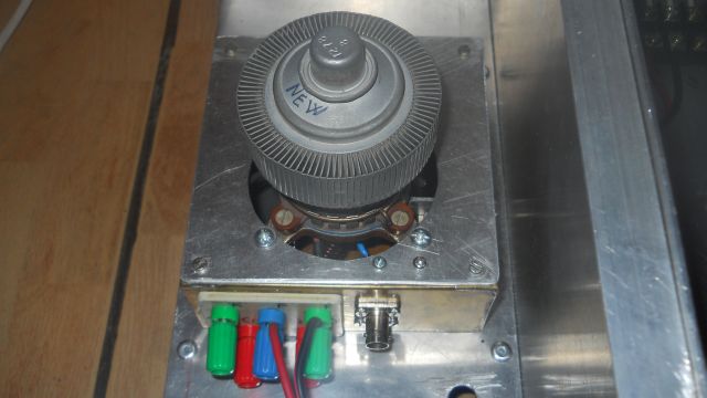
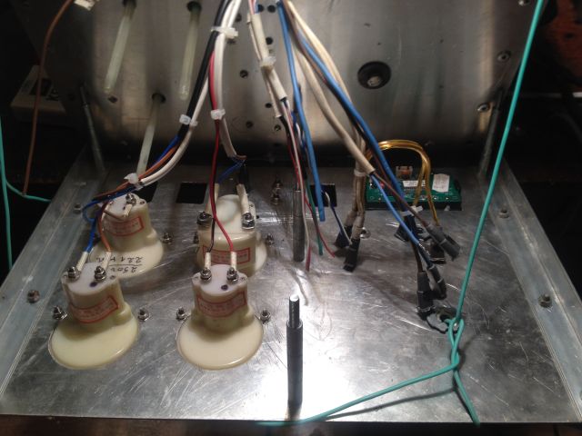
Kathode cavity building
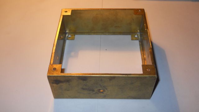
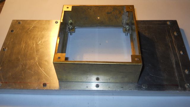
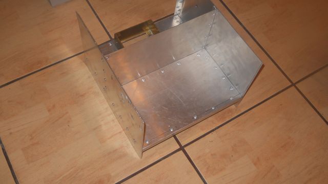
Kathode Cavity Progress
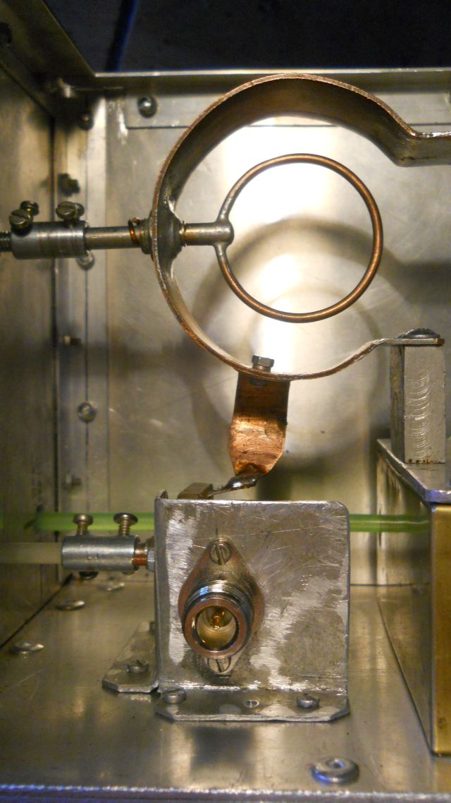
L1 details : 60 mm x 3 mm copper 0,25 mm thick
: single turn, 10 mm diameter, on air

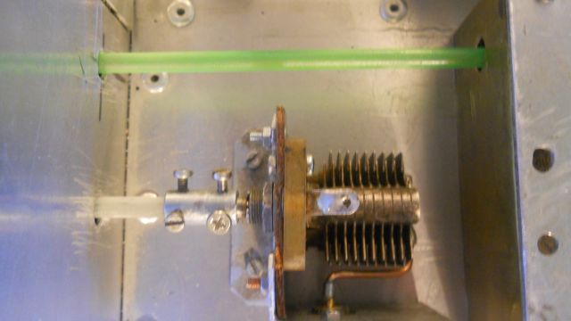
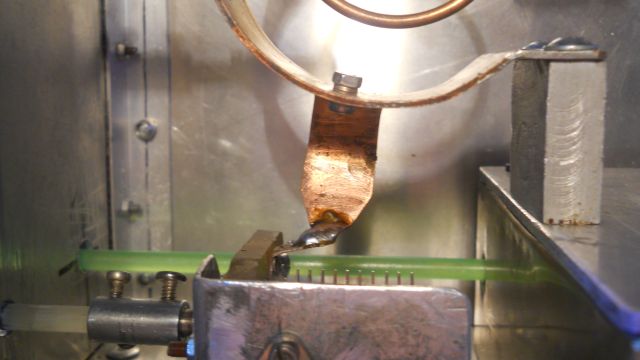
Anode Line Progress
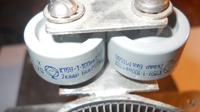
Output Circuit
Anode cavity progress
Tube formatting
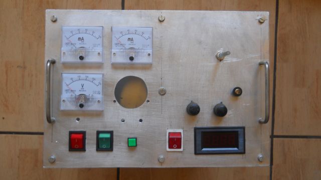
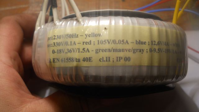
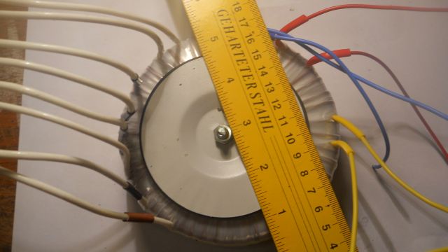
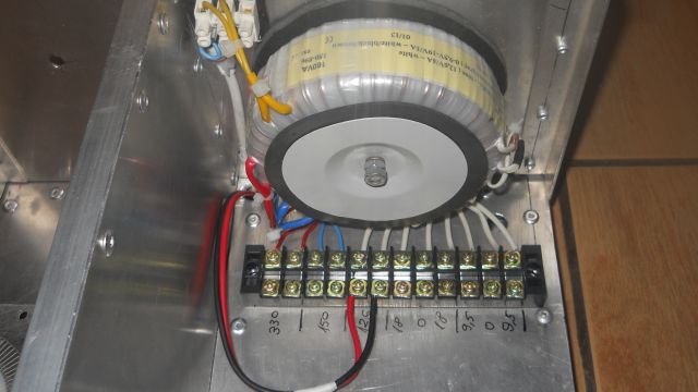
Trafo (160VA) for : G1, G2, Coaxial Relays (12V, 26V, 48V), Heat and Logical Controller from tetrode board.
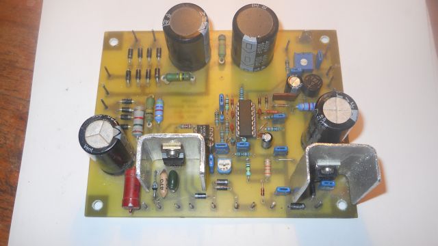
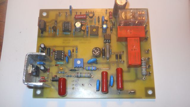
Tetrode board controller based on G3SEK design :
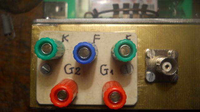
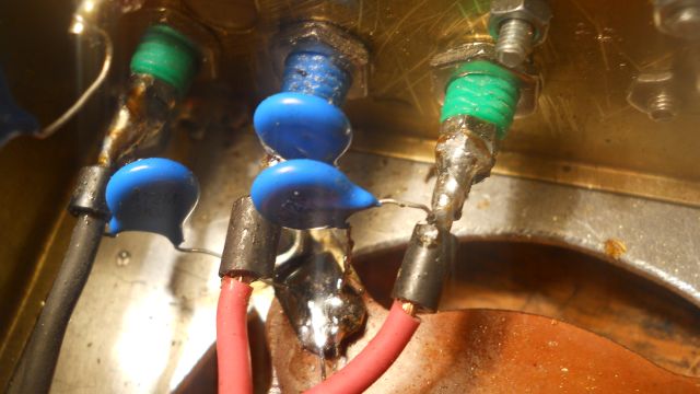
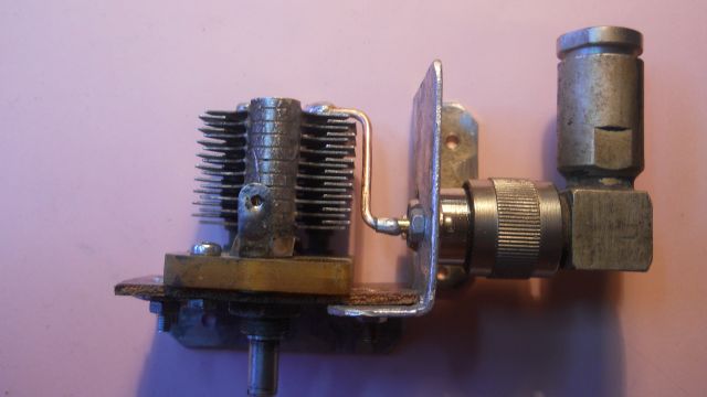
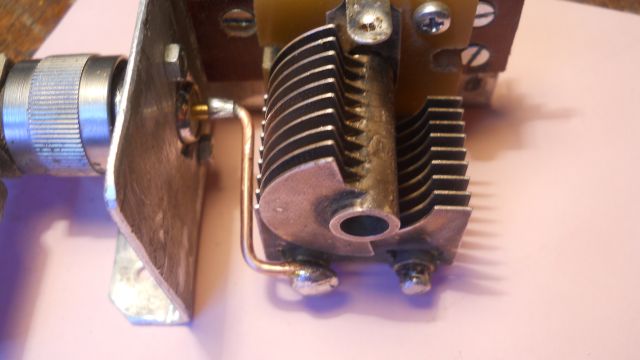
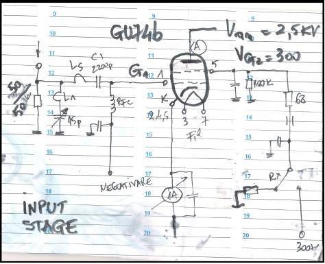
GU74b input stage
http://www.ifwtech.co.uk/g3sek/boards/tetrode/tetrode-1.htm
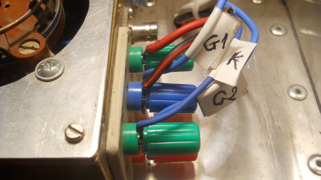
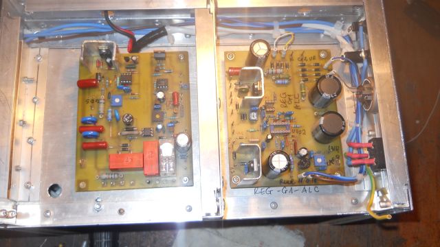
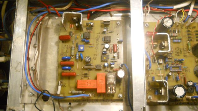
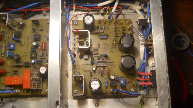
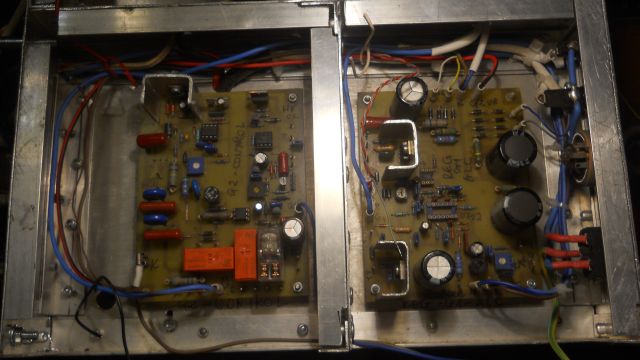
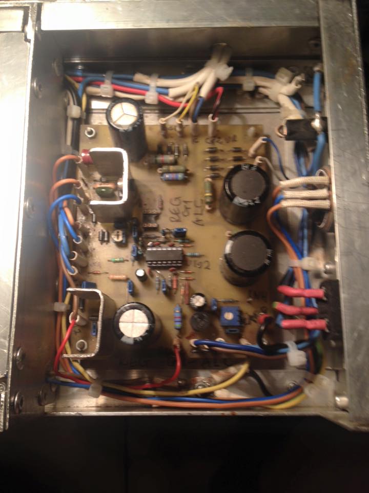
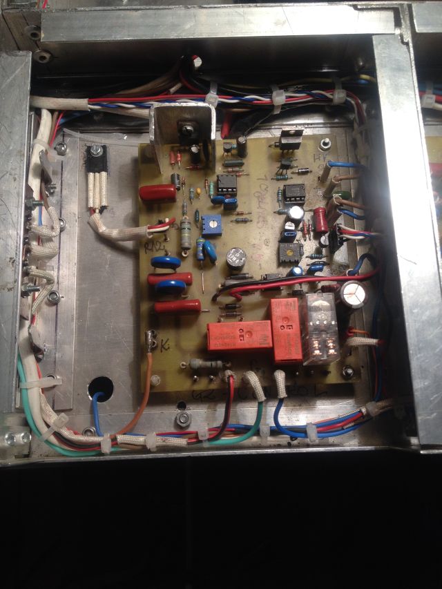
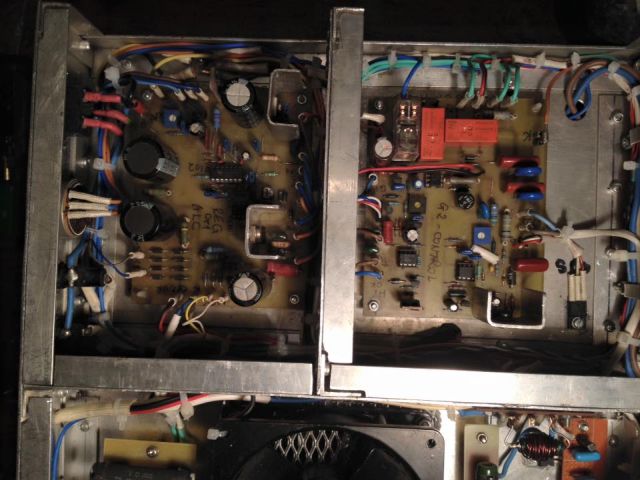
REC-G1-ALC Board G2-CONTROL Board

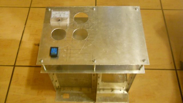
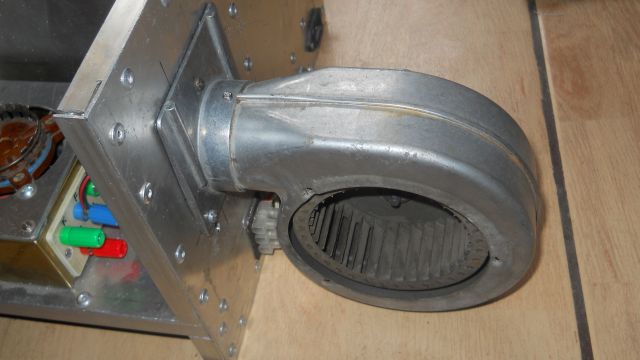
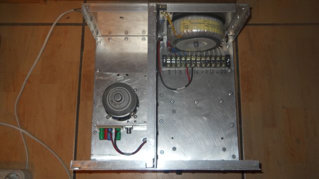
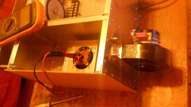
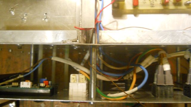
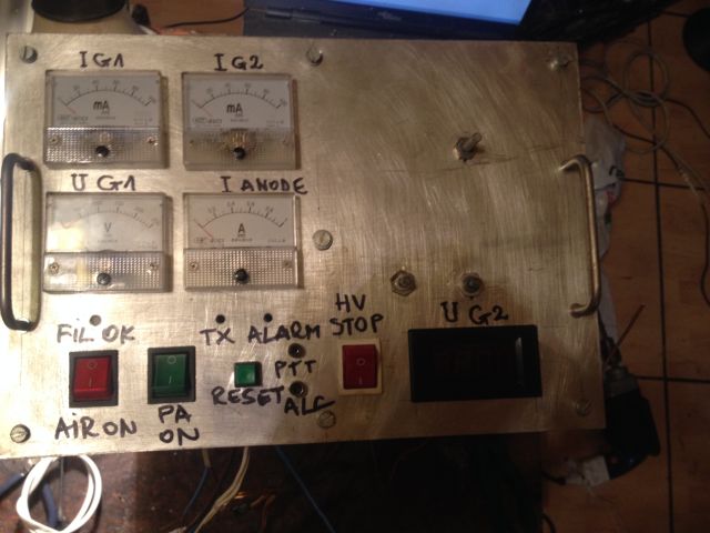
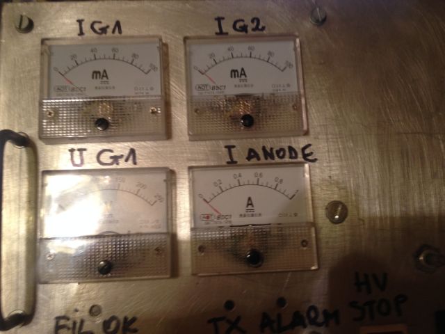
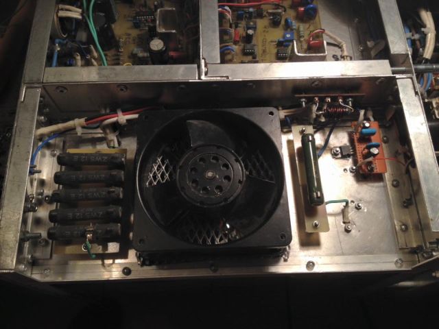
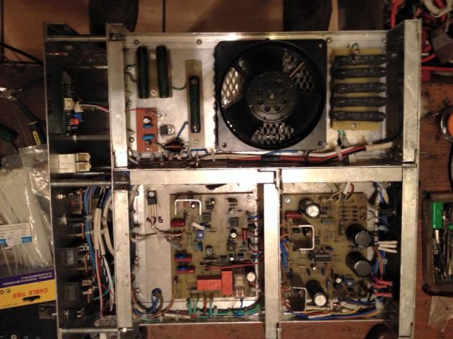
PA progress
Accessories for tetrode board:
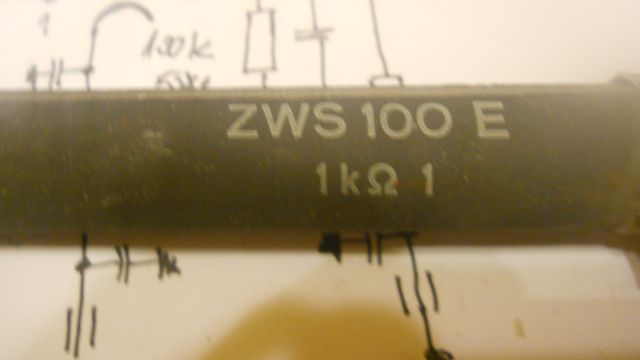
1 Kohm/100W variable resistors 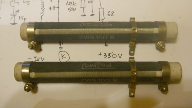
REC-G1-ALC Board ready G2-CONTROL Board ready STP8NK80Z (Q2) - on position
OFF-BOARD COMPONENT CALCULATIONS
1. Rs (SCREEN BLEEDER RESISTOR)
Bleed Current = 10 mA
VG2 = 350 V
Rs = VG2/10 KΩ = 350/10 = 35 KΩ
Rs = 35 KΩ/10W Suggested power = 20W
2. TRIP CURRENT (TO R12)
A = 40 mA
B = 40 x 1,1 = 44 Ma (for each tube)
C = round to next multiple of 10 = 50 mA
Trip Current = 50 mA
3. STANDING CURRENT
Add 20 mA to 50 =70 mA
Standing Current = 70 mA
4. AC VOLTAGE REQUIREMENTS
A = 350 V
B = 350 + 50 = 400 V
C = 70 mA
D = (70 x 0,75) + 350 = 402,50 V
E = round to next multiple of 10 = 410 V
Minimum Unregulated Input Voltages = 410 V
F = 410/1,2 = 341,66 = 342 V
Minimum Transformer Voltage (RMS AC) = 342 V
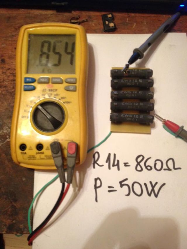
5. R14 CALCULATION
A = 410 V
B = 350 V
C = 410 – 350 = 60 V
D = 70 mA
E = 60 x 1000/70 = 857,14 Ω
F = 60 x 70/1000 = 4,20 W
R14 = 860 Ω/5 W Suggested 860 Ω/50 W
6. R12 CALCULATION
A = 350 V
B = 70 mA
C = (350 – 80) x 1000/70 + 20 = 3000 Ω = 3 KΩ
E = (70 + 20)² x 2000/1.000.000 = 16,20 W
R12 = 3 KΩ/17 W Suggested 3KΩ/50 W
7. R15
Suggested Value For R15 = 82 Ω / 1W
8. RL - SCREEN CURRENT TRIP
A = 350 V
B = 40 mA
C = 350 x 1000/40 = 8750 Ω = 8,75 KΩ
E = 350 x 40/1000 = 14 W
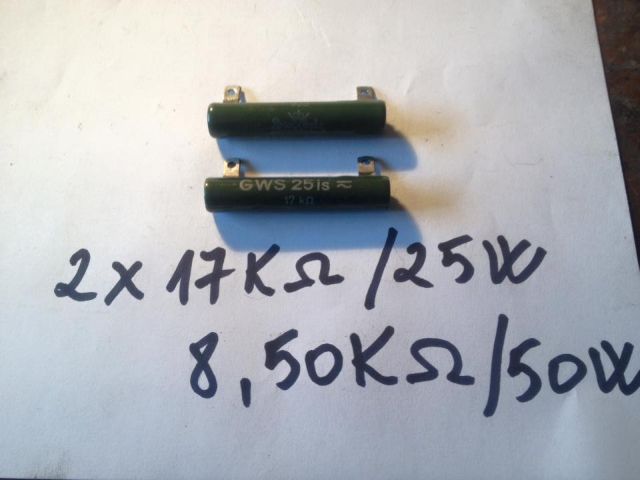
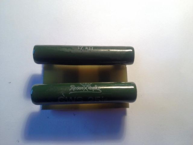
RL = 8,75 KΩ/ 14 W Suggested 8.75 KΩ/30 W
SUMMARY
Rs = 35 KΩ/10W
R14 = 860 Ω/50 W
R12 = 3 KΩ/50 W
R15 = 82 Ω / 1W
RL = 8,75 KΩ/ 30 W
Trip Current to R12 = 50 mA
Standing Current to R12 = 70 mA
TRANSFORMER FOR G2
Minimum Unregulated Input Voltages = 410 V
Minimum Transformer Voltage (RMS AC) = 342 V
Rs = 33 KΩ /30 W R14 = 860 Ω /50W
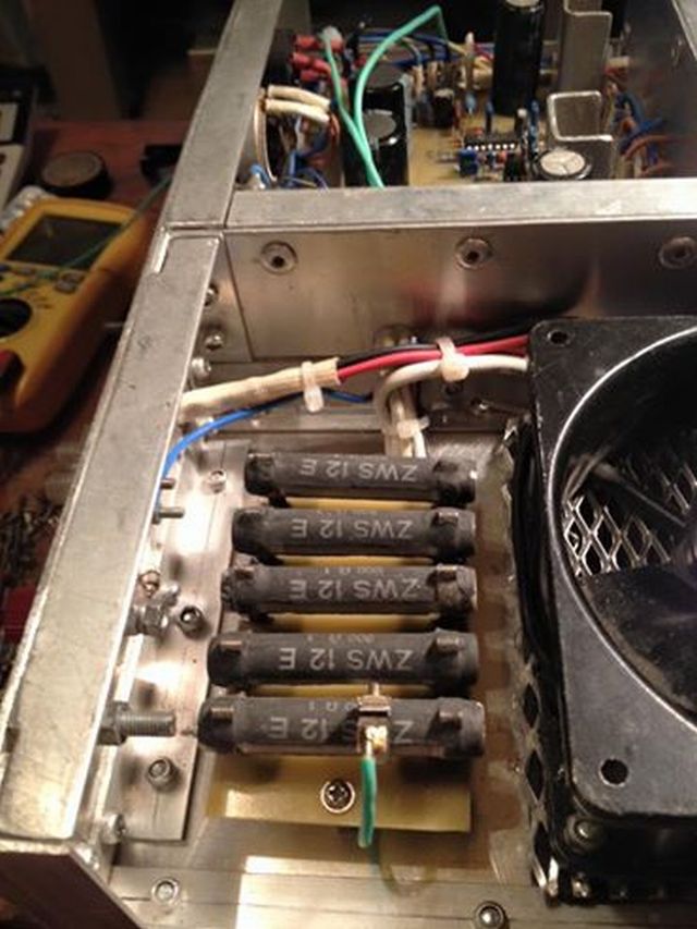
R12 = 8,75 KΩ /50W
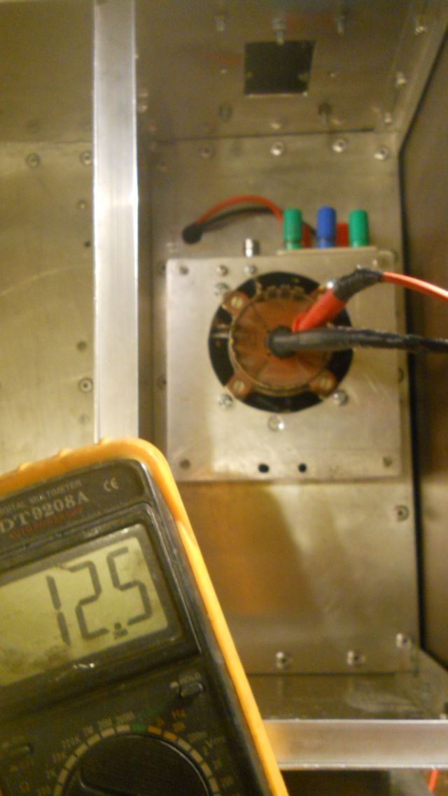
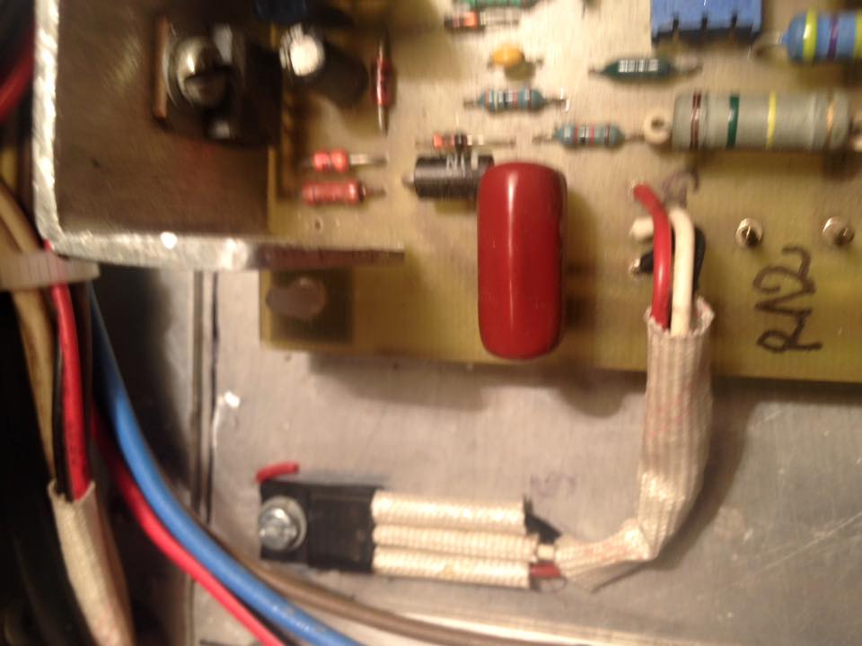
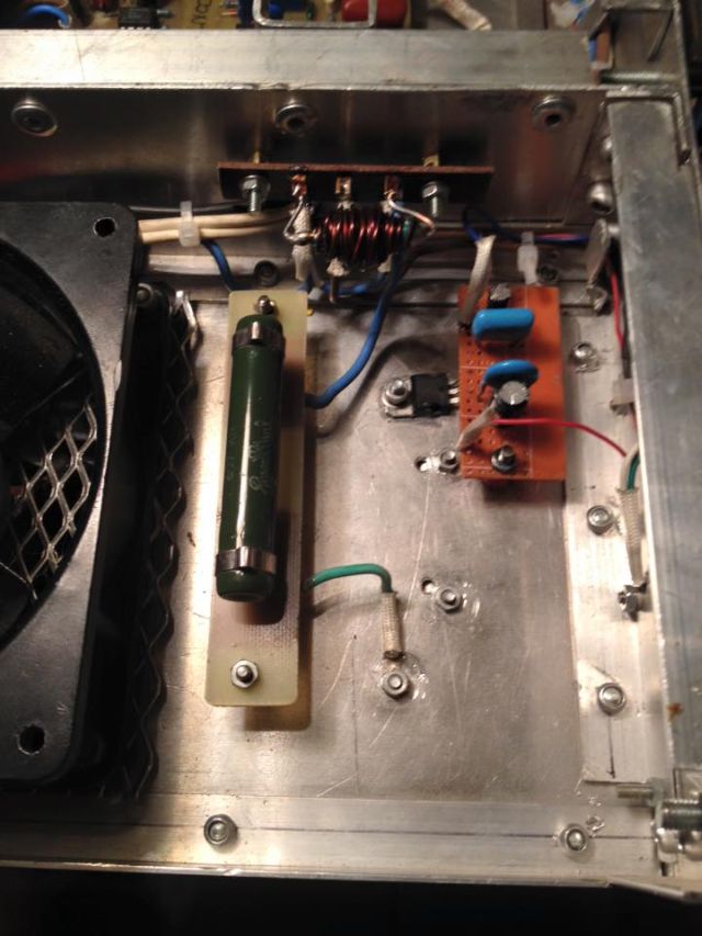
Rs, R14, R12 in position. All devices in position. Final test can start
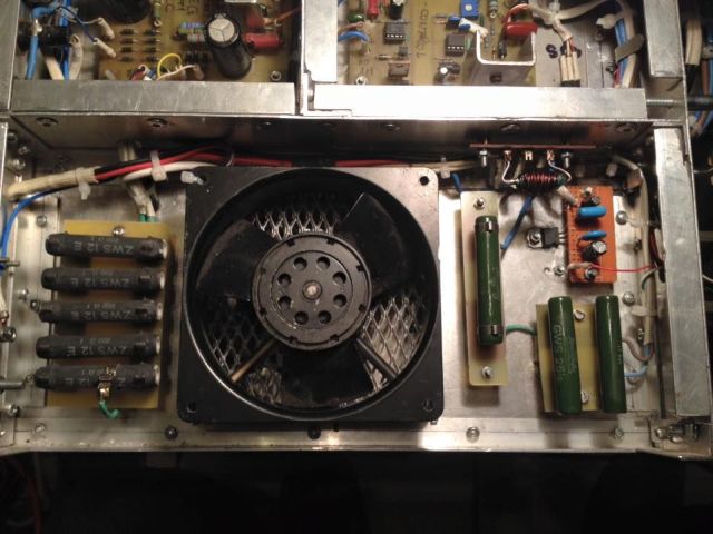
project under construction