<==
<==
<==
(Cont)

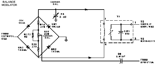
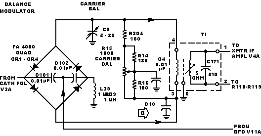
Some early units have a balanced modulator circuit as shown below.If replacing any of these components, recommend replacing with values shown here and in the parts list. Incorporating the changes in produces the circuit shown on the schematic. how ever, these changes are not required and the balanced modulator can remain in the configuration shown below. If the changes are incorporated, all of change must be incorporated.

R 204 and R205, 220 ohms, added; R203 and R206,180 ohms, added; R14 an R16, 47 ohms, were 180 Ohms; and R15, 250 ohms, was 1kW . These changes to the balanced modulator circuit shon in produces the circuit shown on the schematic. If these changes have not been made in the unit, recommend the existing configuration be maintained. These changes
KWM-2 and KWM-2,A Transceivers. Schematic Diagram
figure 7-l (Sheet B)