How Can Phasing Effect Your Signal?
This set of views will give you the opportunity to see the effects of
phasing differences. If you plan to use the same antenna, you will
not have to go through this pain... Some of us just don't know when
to stop!
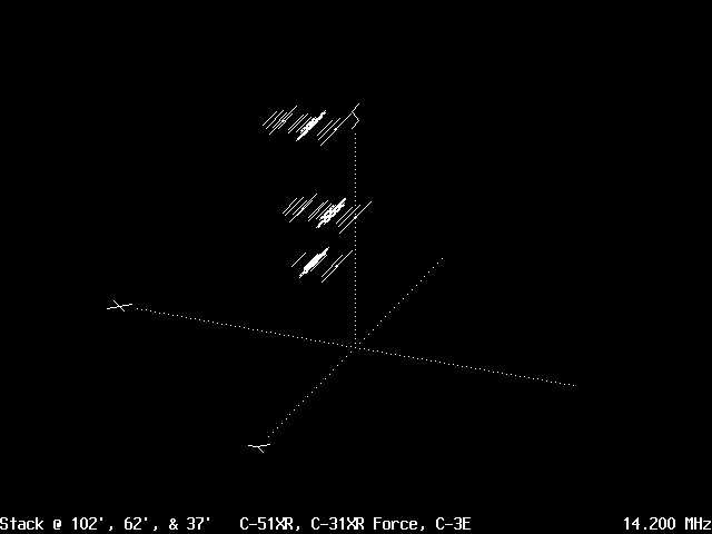
The top antenna is a C-51XR and the driver for 20 meters is located
around 5.5' in front of the mast (center of the tower), the middle antenna
is a C-31XR and the driver for 20 meters is located around 4' behind the
mast, and the lowest antenna is a C-3E and the driver for 20 meters is
located around 1' in front of the tower mast. With all these different
positioned drivers, I needed to find out the phasing effects. Something
important to note is the fact that modeling on only 1 band will not give
you the all encompassing effects. Look at all the effected bands,
in my case that's 20, 15, & 10 meters. I will not show all bands
here, but 10 meters was, by far, the largest improvement.
The set of views include:
Here is the WN9O Antenna Stack Configuration for 20,
15 & 10 meters:
-
Figure 1 (Force 12 Antenna Stack @ WN9O)
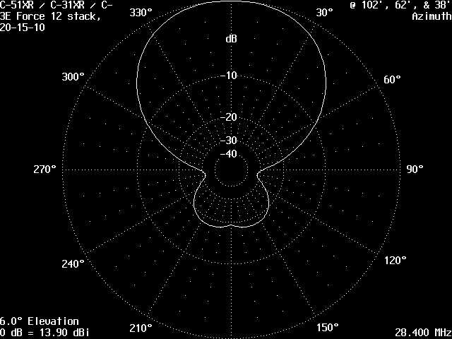
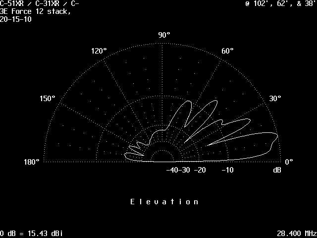
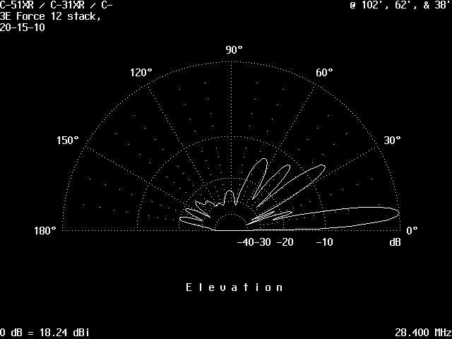
These two patterns are on 10 meters with NO phase adjustment:
-
Figure 2 (No Phase Adjustment Azimuth Pattern)
-
Figure 3 (No Phase Adjustment Elevation Pattern)
-
Note the Numerous LARGE LOBES
-
The Maximum Signal ~ 13°
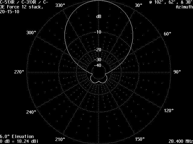
These two patterns are on 10 meters WITH phase adjustment:
-
Figure 4 (Stacked Properly Phased Antennas)
-
Figure 5 (Stacked C-31XR Azimuth Pattern)
-
Note Fewer Large Lobes
-
Almost +3.0 dB of Improvement
Results:
Now how did I find out what phase adjustments were needed? I used
AO to model and best fit my antenna situation. Actually I had lots
of people help with this situation: Jay, WX0B; Jim, VE1JF; and John,
K9UWA. After building the models, John and Jay did optimizations
with AO. They gave me the results and I compared them with what I
had calculated. I modeled 20, 15, and 10 meters and now have some
phasing solutions.
The phase delay of the above models show a phasing difference of C-3E
@ 38' (0° Phase), C-31XR @ 62' (-24° Phase), and C-51XR @
102' (-114° Phase). If you only look at the gain on the 6°
elevation plot, the non-phase plots show about -3 dB down from the phased
plots (in essence you lost your gain from the stack). Now the job
of cutting the phasing lines....
Cutting the Coax :
As I stated the 10 meter phase difference between the C-3E and C-51XR
is around 114° and I am using Belden 9914 coax, so I calculated the
length to be:
Coax Length = (SOL / F) / 360° * PD * VF
SOL = Speed of Light = 984,000,000 ft/sec
F = Frequency = 28,400,000 cycles/sec
PD = Phase Delay = 90°
VF = Velocity Factor = 78° (Belden 9914)
Coax Length = (984 / 28.4) / 360° * 114°
* .78 = 8.55 '
After talking to Jay, WX0B, he indicated you could also take a dual
trace oscilloscope and connect the coax directly into the inputs and have
a local transmission aid in determining the phase shift. When you
adjust the coax appropriately the signals will arrive at the scope at the
same time.
Bottom Line:
If you need help determining the phase difference, just start modeling
with NEC or AO. If you still need help, the one thing I will mention
is the prompt service I have received from Jay. Even though he is
growing the company "Array Solutions", he has always made time to answer
my questions and help me solve problems.
top || back
|| WN9O home