
| The following is a pictorial for building the Version 2 (Date on board: 6/25/2008) Stabilizer board. There are ten steps to complete board. |
Install the .01 capacitors and resistors.

|
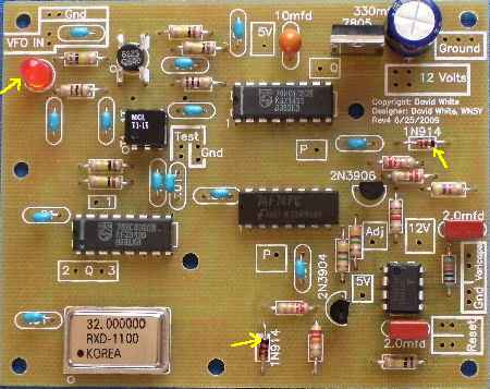
Use a Volt-Ohm Meter to double check resistor values. The proper placement of the 4.7 meg resistors is very important. Start with the .01 capacitors. Place 7 on the board, solder, place the other 6 and solder. Place 5 resistors at a time on the board and solder. Placing too many on the board at a time could be confusing and result in missed solder joints. You will have 2 100K resistors left over. They are used on Board 1 when the varicaps are installed at the same location. See the yellow arrows in the above picture for correct placement of the 4.7 Megohm resistors. Step 2Two 2.0 mfd capacitors and a 10 mfd tantalum capacitor
 The two capacitors that are square and marked 205 are located around the CA3140. They have thick leads. Make sure solder flows on the leads and get a good solder joint. The 2.0 mfd capacitors are very important for excellant stabilization. Install the 3 pin 10 mfd tantalum capacitor. Orientation does not matter. Step 3100 mfd Electrolytic
 Note that the 100 mfd is a polarized electrolytic capacitor which needs to be placed with the positive lead (the long one) in the hole labeled "+". The short lead is the negative (also marked with a vertical band with a "-"). |

|
Install the T1-1T transformer. Note the DOT on the transformer and place next to the "o" on the footprint. Note the black arrow that points to the "o" on the PCB. |

|
Solder the two 74HC4020 ICs and the MOSFET to the PCB. IC sockets are not included with the kit, but may be used if desired. Pin 7 and Pin 16 on the ICs can be easily overlooked. Double check to make sure you have them soldered. You do not have to solder unused pins. |

|
Solder the 32 MHz Oscillator on the board. Notice the Dot on the Oscillator can and match it to the "o" on the PCB. Note the arrow in the picture. |
|
Solder the 5 Volt Regulator on the board. Note that the front of the regulator is facing toward the outside of the board. The thick line of the footprint represents the heat sink. Look at the picture before installing. Solder the CA3140 amd the 74F74 (or 74S74) on the board and match the notch of the ICs to the notch of the footprint. Note the arrows in the picture. Double check that you have Pin 1 on the 74F74 (or 74S74) soldered. You do not have to solder unused pins. Solder the transistors on the board. Match the flat side of the transistor to the flat of the footprint. Spread the leads of the transistor to match the holes in the footprint. Press in gently, do not force in too far. |
|
Note the black band on the diode and match to the white band on one end of the footprint. Note the arrows in the picture. Bend the leads away from the diode about 1/8" to match the holes in the footprint. Be carefull, the diode is made of fragile glass. The led has a flat on one side that must be matched to the flat on the footprint. The flat is the negative side of the LED and is also indicated by the short lead of the LED. Note the arrow in the picture. |

|
The length of the four jumpers are as follows: "Q" - 4" - Connect Q2 to Q Number 24 wire or smaller, either standed or solid, works best to fit the holes in the board. |

|
Make 8 loops by wrapping a 1 1/2" bare wire around the end of a needle nose pliers three turns, then unwrapping the last turn, spread apart the wires to fit the holes in the PCB. Note the yellow lines in the picture above for locations: 1. 12V and Ground Back to Construction of the PCB - "Connecting to the Receiver" to continue installing the Stabilizer. |
Send E-Mail || Amateur Radio Receivers || Electroluminescent Receiver
