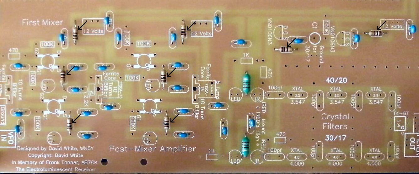
To learn about the First Mixer, read the
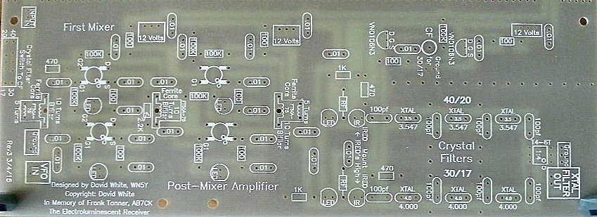
Circuit Details - First Mixer & Amplifier
before building this section.
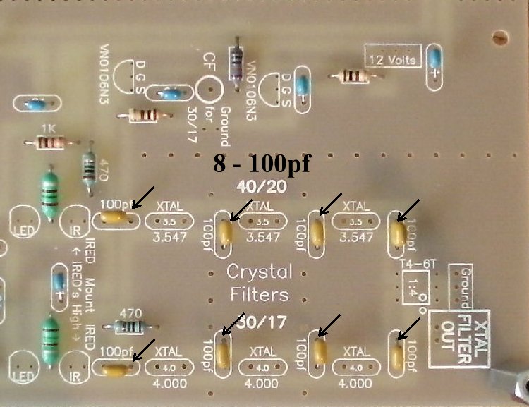
To learn about the Crystal Filter, read the
Circuit Details - Crystal Filter
before building this section.
|
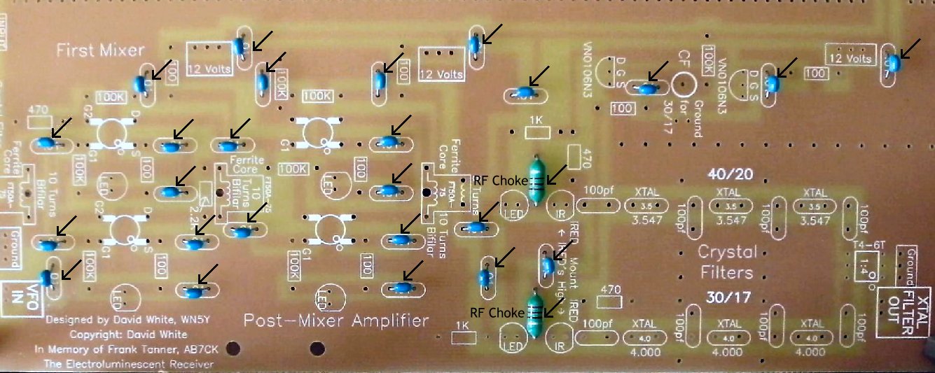
Insert all the components that have their values inside the footprint. They are the following: ____2 - RF Chokes (Bag 3), Footprint on PCB is rectangle with square edges, "RF" inside the rectangle. Choke is about the size of a 1 watt resistor with rounded edges. Solder ____25 - .01 capacitors (Bag 3) |
|
Solder |
|
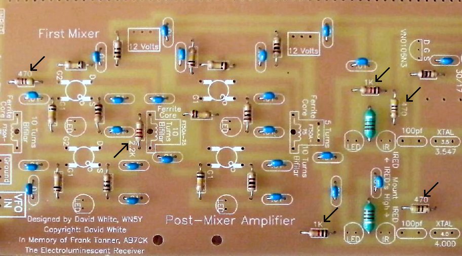
____8 - 100 ohm resistors (brown, black, brown) (Bag 3) |
|
Solder |
| ____8 - 100K resistors (brown, black, yellow) (Bag 3) |

|
Solder |
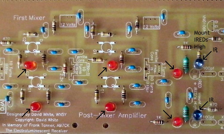
Resistors:____3 - 470 ohm (Bag 4), One is located at the top left of the first mixer, and the other two are located to the top and right of the IR LEDs. |
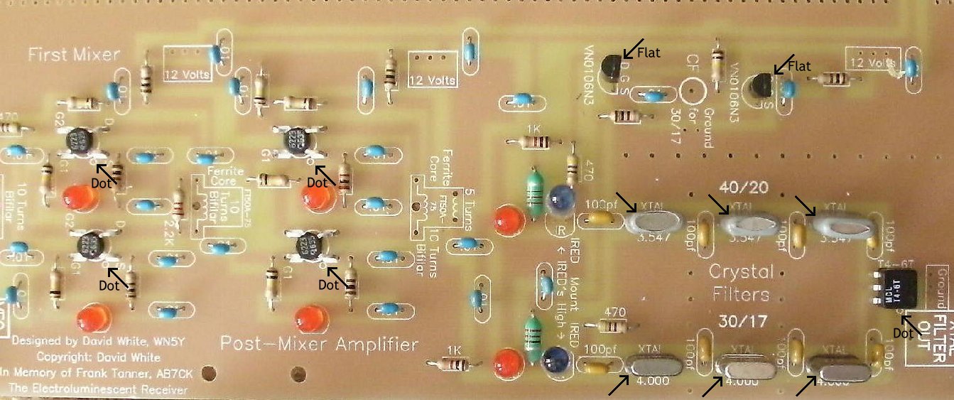
Capacitors____8 - 100pf NPO caps (Bag 3), Orange color, short leads flared out, labeled "101". All located inside the crystal filters. |
|
Note: The value of the capacitor you use in the filters determines the bandwidth. If you want all SSB, change the caps on the 40/20 (3.457MHz) filter to 39pf (not included in kit, any value cap between 27pf to 39pf will work) for best reception. The 100pf caps on the 30/17 (4.000MHz) work fine on SSB. If you are CW only, raise all the capacitors to 200pf, after you have the receiver working. When raising the value of the capacitors, solder the new ones underneath the board to the existing capacitors. Taking out the existing capacitors can be a lot of trouble and you may want to revert to the old values at some time in the future. Solder |
Other Parts:____6 - LEDs (Bag 3), Red colored, match the flat on the LED to the flat on the footprint. The short lead is on the same side as the flat. Note: If you ordered the Super Bright LEDs, you can place two of them at the input of the crystal filter, next to the IR LEDs. Use different colors to help crystal filter identification. If you ordered the Bright Red LEDs, they can replace the ones in the mixer. See Modifying the LEDs. Solder |
|
____2 - IR LED (Bag 4), Smoky colored, on a cardboard strip, do not cut the leads off the strip, tear the IR LEDs off the strip and clean the bottom of the leads. Located at the input to the crystal filters, right next to 100pf caps. Mount high on board, with the leads through the board just enough to solder underneath. The short lead is on the same side as the flat. Mount as high as possible and match the flat on the LED to the flat on the footprint. Bend the one shown above, in the middle of the board, toward the Phototransistor at the VFO board. Aim the phototransistor back toward the IR LED. The IR LED near the outside of the board points to the phototransistor at the Crystal Oscillator on Board 2. Wait till you mount the boards to aim this IR LED. |
|
Solder |
|
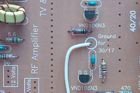
____2 - VN0106N3 (Bag 2), static sensitive part, touch a ground lead before removing the part from the bag. Match the flat on the part to the flat on the footprint. Spread the outside leads slightly to fit the footprint. Marked "SI N, 0106, 8302". A dot is placed outside the footprint so that you can double check your placement after it has been soldered to the PCB. The leads on each side of the part need to spread apart slightly to fit the footprint. Solder ____3 - 3.457MHz crystal (Bag 4), Has a gray plastic cover over the crystal with the markings "NYMPH C O 17915-03". Note: 99% of all the crystals we have tested have been within 100Hz of each other (both values), so no matching is necessary.____3 - 4.000MHz crystal (Bag 4), The markings are "4000 KSS 2FT". Solder ____1 - T4-6T Minicircuits 1:4 transformer (Bag 4), Note: Tin the leads for this is a difficult place to solder the transformer because of the small pads. Wipe the excess solder to the top of the pin so it will fit in the holes. |
|
Note the dot on the part and match it to the dot on the footprint. A dot is outside the footprint so that you can double check your work after it is mounted. Located at the output of the crystal filter. |
|
Solder |
|
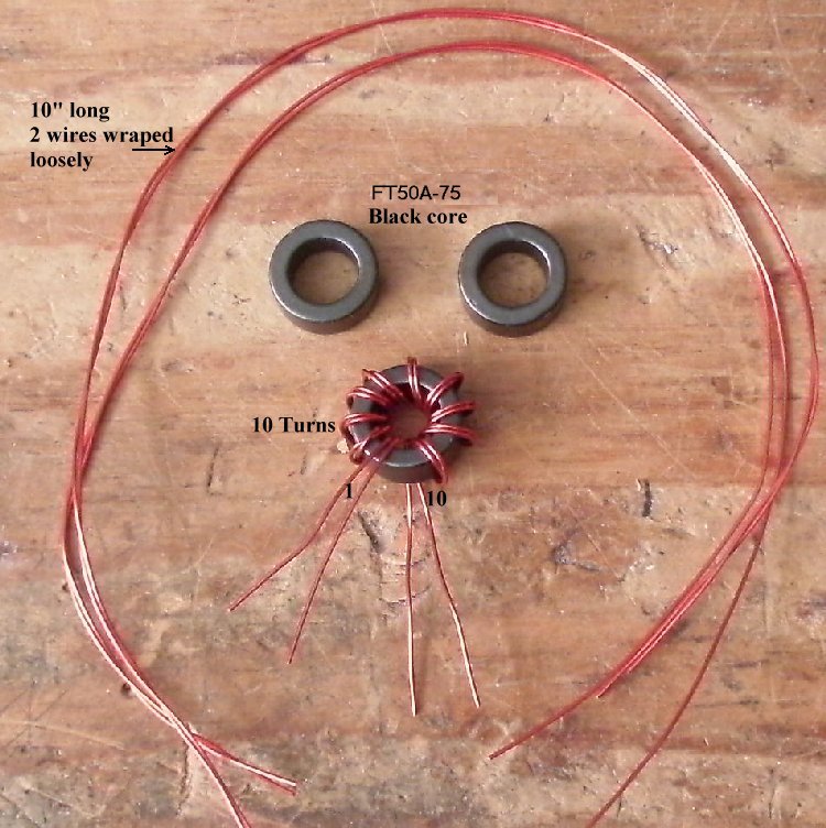
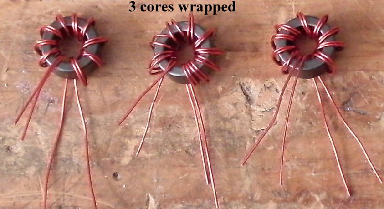
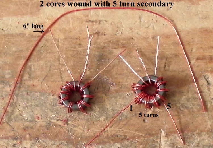
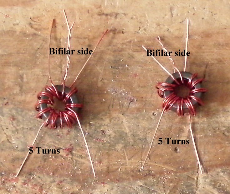
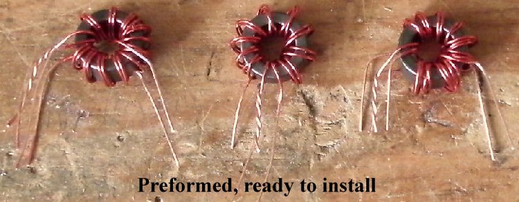
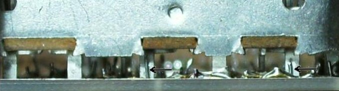
____2 - FT50A-75 Ferrite Cores, enamel wire (Bag 4), Cores are wound with a Bifilar winding and a 5 Turn winding in the "Preparation" section. These are located at the ends of the Mixer/Amplifier. Be careful to get the windings soldered on the board correctly according to the footprint. The lead that has two wires goes in the middle hole. ____1 - FT50A-75 Ferrite Core, enamel wire (Bag 4), Core is wound with a Bifilar winding in the "Preparation" section. This core goes in the middle of the Mixer/Amplifier. Winding and Installing the FT50(wide)-75 Transformers |
|
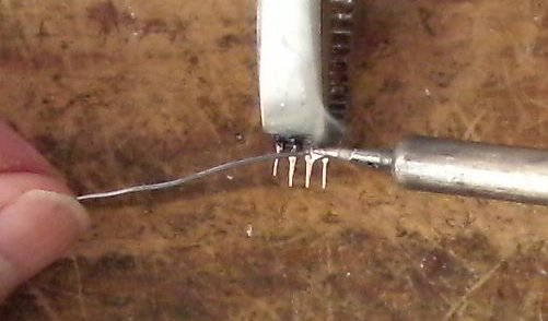
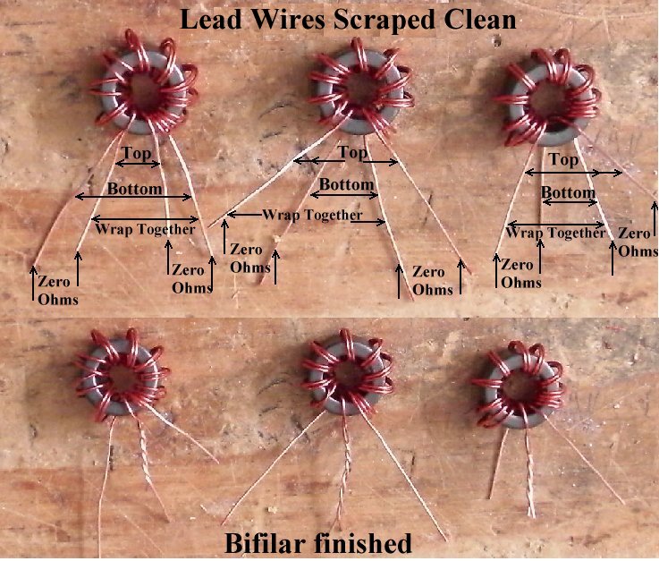
Scrape the lead wires of their enamel coating. Use a VOM and arrange the wires as shown in the picture below putting the ones having continuity (zero ohms) on the same side. Wrap one wire from the top to the opposite side bottom wire. |
|
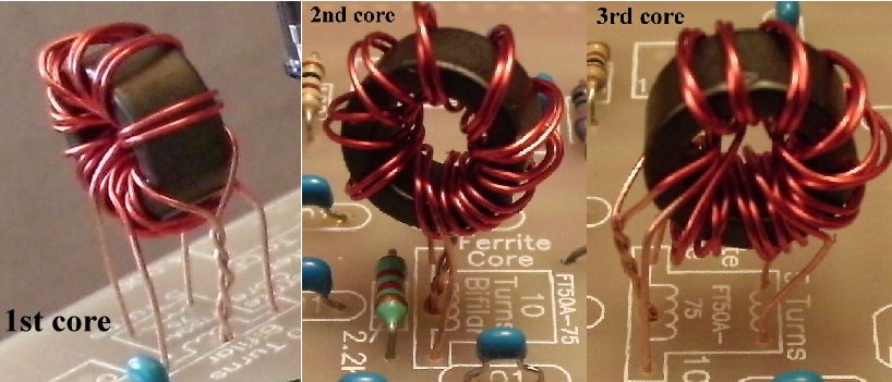
If you need additional help, click on the link below. Two of the Bifilar windings need a 5 turn Secondary |
|
The cores are high off the board in the picture above to show the connections. After you have it right, push the core all the way down to the board, or slighly above. Don't leave them high like in the picture.
Solder Please Check!Carefully inspect the wires on the bifilar side of the cores and make sure they are not shorted. There is no ohm meter check for this error, so you must look carefully. Make sure the bare parts of the wires are not touching! Double check underneath the board to make sure there is not a solder bridge between the leads. The second and third core (counting from the front) carry 12 Volts. If the bifilar leads are shorted there will be some burning (smoke) of the wires, the LEDs will not light up, and the 100 ohm resistor that feeds 12 Volts to that core will need to be replaced if it is black or shows open with a VOM. |
|
____1 - SPDT Miniature PC Mount switch (Bag 5), There is a switch footprint in front of the First Mixer. There are two hole patterns. Mount the switch in the holes that work. |
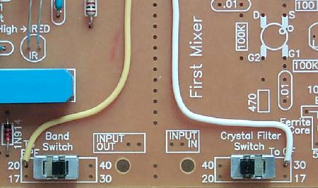
____7 1/2" wire - Between the VN0106N3's, there is a BOLD circle that is labeled "Gnd for 30/17" and marked "CF". Solder a 7 1/2" length of wire to the circle and to the terminal marked "To CF" on the Crystal Filter switch.
 |
|
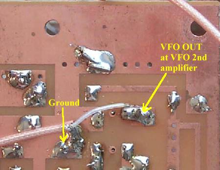
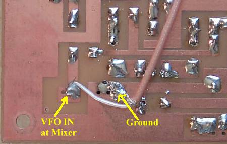
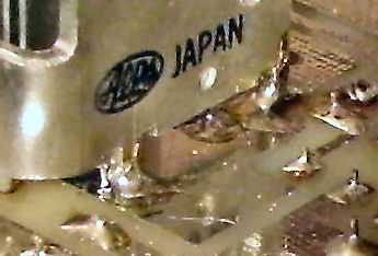
The coax supplied with the kit is Teflon 50 ohm cable. The best way to strip the insulation is to get a very sharp utility knife and slice a 1" section length wise, then fold over the cable and pull the shielding/center out of the insulation. Pull back the shielding slightly to loosen, make a small hole at the bottom, and pull through the center wire. Since it is Teflon, there is no of danger burning up the insulation on the center wire and causing a short while soldering. Pictures and Instructions for using the Teflon coax.Best to mount this jumper underneath the board for a cleaner appearance and avoid interfering with the IR switching at the bandpass filters. When soldering underneath the board, solder to the traces and the ground plane. Saturate the ground braid with solder first, then solder the braid to the ground plane. Next solder the center wire to the output(VFO OUT)/input(VFO IN) pads. |
Making and soldering the 'XTAL FILTER OUT' coax cable____Miniature Coax Cable, cut a 10" piece (Bag 6). Strip and prepare as explained above. ____Solder the center wire to "XTAL FILTER OUT", solder the braid to the "Ground" box. Leave the other end loose at this time. 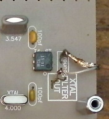 Using Wire Loops would be best. |
|
____Place the PCB in front of a bright light. If you see light shining through any of the soldering holes, you missed a solder connection. |
|
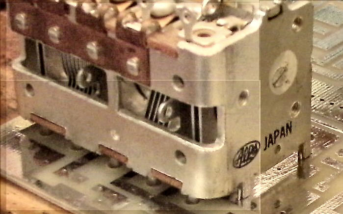
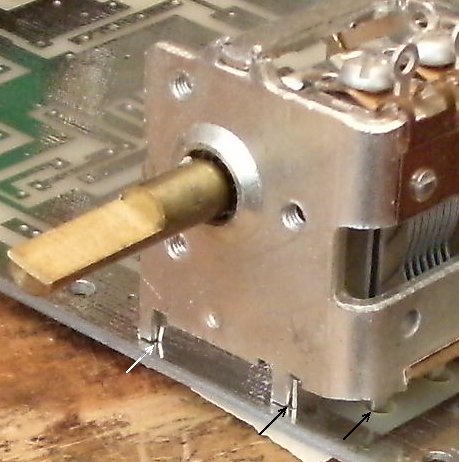
Note that a clean board is used to show how to mount the main tuning capacitor. This was done for clarity. Your board will have parts on it and underneath the board will have many soldered places. Take a little time to inspect the solder joints that will be covered up by the tuning capacitor and make sure they are near perfect. Reaching them with the capacitor in place is possible, but troublesome. The yellow trimmer and the relay in the area should be checked very carefully as they are the most difficult to solder and will cause the most trouble if not soldered correctly. Use a magnifying glass! |
| ____1 - 5 section tuning capacitor (Bag 1), Note the double holes inside the footprint of the tuning capacitor: this is where the mounting legs of the capacitor will mount underneath the board. |
|
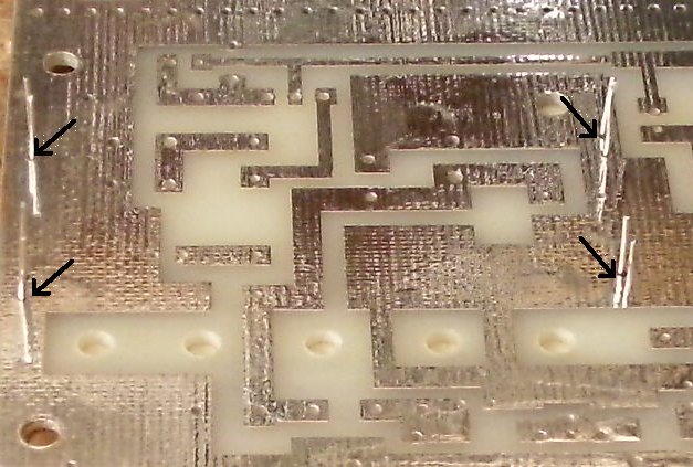
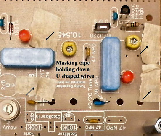
As shown above, get four (4) of the resistor lead trimmings. Using needle nose pliers, bent them in a U shape with about a 1/8" flat. This means bending them right at the tip of the pliers. Run them through the capacitor hole mountings from the top. Cut small pieces of masking tape (or any sticky tape) to hold them against the top board. |
|
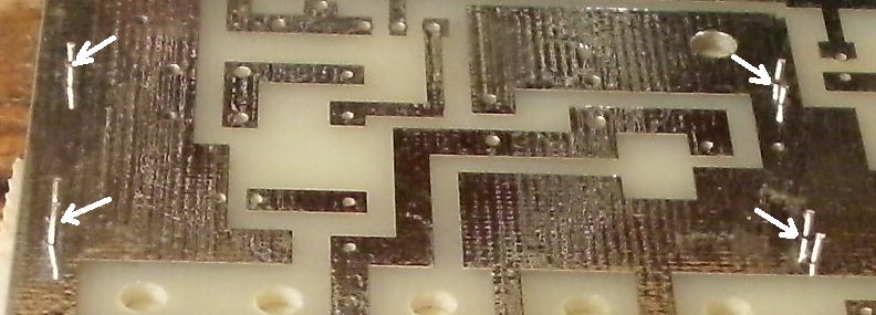
Trim each leg of the U shaped pieces to about 1/8" long as shown in the above picture. The legs of the capacitor are just a hair longer than 1/8" Pull the NPO capacitor leads (the 2 caps that will be connecting to the soldering lugs) from the top of the board up out of the holes. Tin the capacitor mounting legs so it will be easy to apply solder to them as shown in the following pictures. Be sure to apply enough heat to the legs so that they accept solder. You may need to use a slightly larger tip (and higher temperature) on the soldering gun so that more heat can be applied to the joint. |
|
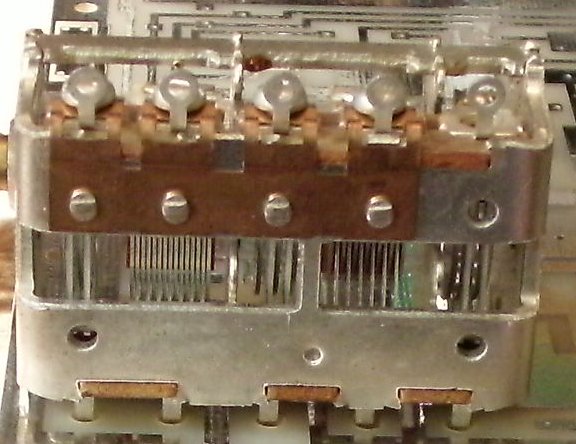
Lay the tuning capacitor on the board beside the U shaped pieces and slide the capacitor until the side soldering lugs are directly above the holes. The capacitor lugs should fall down into the holes very slightly. The legs should slip in between the U shaped pieces and the capacitor should be straight and the soldering lugs in the holes. |
|
When the capacitor looks like the above pictures with the U shaped wires hugging the legs of the capacitor, solder very carefully. Solder the wire onto the leg first. Check alignment, and then pour solder down onto the ground plane too. After one leg has been soldered in place, then the others should be no problem. |
|
After the capacitor has been mounted to the board, solder the 39pf capacitor to the middle tab, and the 10pf to the back tab of the capacitor, as shown on the silkscreen and in the picture below. |
|
The tuning capacitor wire of the 10pf capacitor should be trimmed 1/2" so it is not too high in the air above the top of the board. If you have the 39pf with the short leads, you will use the entire lead length. The 39pf with longer lead length will need to be trimmed 1/4" to 3/8". The leads of the capacitor need to be on the side of the lug that faces the edge of the board. Then a small tipped soldering iron can reach through to the lug and solder the lead to the solder lug. Carry a bit of solder on the tip of the iron to solder the leads to the lugs. Standing the board vertical (the standoffs on the board corners will help) with the tuning capacitor at the top will make it easier to solder. |
| You can test Board 1 now, then build and test Board 2, or build both boards, then test both after you finish. |
Send E-Mail || Amateur Radio Receivers || Electroluminescent Receiver || Back to Basic Instructions