
Q-Multipying Mixer
This project was the result of attempts to reduce images in superhets with very low IFs, either as a complete front end for a single conversion super, or as a stand-alone converter for receivers such as the BC-453, when coupled with a crystal (or other) oscillator to produce a difference frequency at it's output.
What is shown in the circuit is the regenerative RF pentode amp. It is very similar to what was used in several of the "Double Regeneratives" of the 1930s. Making it into a converter means simply introducing the output of a local oscillator to the cathode of the pentode, here shown a 6J7.
The Q-dyne can serve as a front end for a regenerative receiver, having a fairly broadbanded output for a detector to tune across when inductively coupled to the untuned output of this device. Passband sharpens when regeneration occurs as needed. In this service, it is tuned separately from the detector.
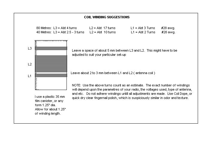
As seen in the circuit, the Q-dyne is simply a regenerative amplifier, similar to a regenerative detector. Both utilise some form of feedback arrangement, to return some of the output in phase to the input. The Q-dyne uses the very familiar method of employing a tickler coil in the plate circuit. Other variations exist, such as a cathode return arrangememt. Control of the feedback in our case is accomplished in the cathode circuit by a control pot of about 20k ohms. You may need to experiment a bit with ticker winding and pot values. Wind L1, 2, and 3 in a similar manner as is done with my regenerative 2 stage receiver, only remember when you view the link to the coil that L1, 2, and 3 are labled differently on the regen circuit than they are on the Q-dyne circuit. ( View Coil ).
The Q-Dyne converter, which is simply the above mentioned circuit injected by a local oscillator to produce a difference (or sum) frequency, is essentially the same as that found in my Regenerodyne example, only made regenerative by the addition of L2. The main difference is that the Q-dyne converter is built as a stand-alone circuit which feeds my BC-453. The same 6C5 Pierce xtal oscillator is used. You can use any other type you might fancy. I like the Pierce for simplicity and that all important parts count.
(Hopefully, as I can manage some acceptable images, I will post them) The overall layout of this project is not too awfully critical, assuming the normal construction peridigms of direct connect short leads, keeping heat generating components from items which determine frequency, keeping grid circuitry away from A.C. on the filament leads are observed. As mentioned earlier, my particular version of the Q-dyne is built into the same enclosure which houses all of the other outboard wiring for my BC-453, namely the audio gain pot, the AM/CW switch, power switch, audio output jacks, and stand-by switch. Since I have aligned my IFs for single-signal reception, it was incumbent upon me to determine which xtals to use in my converter for lower sideband reception for SSB on 40 and 80 metres, the 2 bands I use the BC-453 on.
Note the photo at the top. What you see is the Cabinet that houses the P.S., Q-dyne converter, speaker, and all outboard wiring for the BC-453. The attached box on the cabinet left is the reactance control, added after I converted the mixer to a regenerative mixer. It houses the cathode pot, and a fine tuning cap for critical tuning of the front end . Thanks, John, for letting me borrow your little digital camera. I am now going to drop hints for a christmas present.
I just happened to have a few old Johnson Messenger 1's at my disposal, so I gutted one for use as sort of a control head for the '453. The cabinet front panel is soft enough to work easily, and the chassis is all aluminum, great to re-work for small projects, and happens to be the perfect size for ARC-5 add-ons.
I had lots of room in the White Face cabinet to put the power supply a respectable distance from the front-end converter. However, I did run out of room on the front panel to run the reactance control (regeneration control) when I converted it to a Q-Dyne, so I placed it in a small metal enclosure, and bolted it on the side of the cabinet. Only one shielded wire was needed to connect the control pot to the cathode. For very precise critical tuning, I would advise the employment of a vernier device for peaking the front end LC, or a "band-spread" parallel variable cap. The reason for this is that in order to tune for ultimate maximum threshold, you have to critically tune the front end. Personally, I keep it somewhat under threshold, except for rare occasions when I needed to haul out a really really weak signal, and the broadcasters were really problematic. I went for a short antenna and maximum gain. Sometimes it helps.
I keep the xtals within the cabinet, switching between the two (for 7.0 - 7.2 and 7.2 - 7.4 mc coverage, respectively). The xtal switch obviously becomes a band selector switch, when I switch from the 40m xtals to the (one)80m xtal. Of course, when changing bands, you also must re-tune the front end LC.
Obviously, I was impressed by the performance of the regenerative, or "Q-dyne" amp/ converter, otherwise I would not have posted it here. While it is not a cure-all for image ills or a replacement for the collins mechanical filter, for a simple circuit employed with a simple receiver, it has been well worth the effort. In my version, the most noteable enhancement was volume. This benefitted the '453s soft audio stage. The second rather predictable item is increased selectivity. To be truthful, I was not able to absolutely rid myself of the very strong maritime birdies: but the closure of these stations last year solved my problem. Oddly . . . I'd rather not that be the solution. I will miss the CW maritimes. I would have rather put up with the birdies. There were other images that were annoying during daylight hours on 40m that were greatly attenuated.
Operation is simple enough: tune in the signal you want to hear and begin to advance the reactance control. As you do, the signal will noticeabley increase in volume. Re tune the front end LC for maximum loudness, and advance reactance again, re peaking the front end, and so again repeating the process until you reach your desired effect. Do not advance the regeneration any further than you need it. Once you have the Q-Dyne tuned, you should be able to keep it tuned for several kc's until you need to re-touch the input LC (antenna tune) again.
Well, that's about it, except for the photos of my version, which (hopefully) should be forthcoming. Any questions, feel free to ask me at [email protected] or [email protected]. It's an easy project using easy to get parts. It has lots of potential, when properly utilised. You might consider using it ahead of a weaker receiver to help out it's performance. Or a SW to broadcast band converter. Just figure the output frequency you need and order xtals accordingly. HC-6 xtals work fine. As a suggested local oscillator, try the xtal Pierce that I use on the regenerodyne page, in the same way I use it as shown.