The Novice Special: An Old Classic Revisited
By Gary Johanson, WD4NKA
Photos and images may take a little time to download
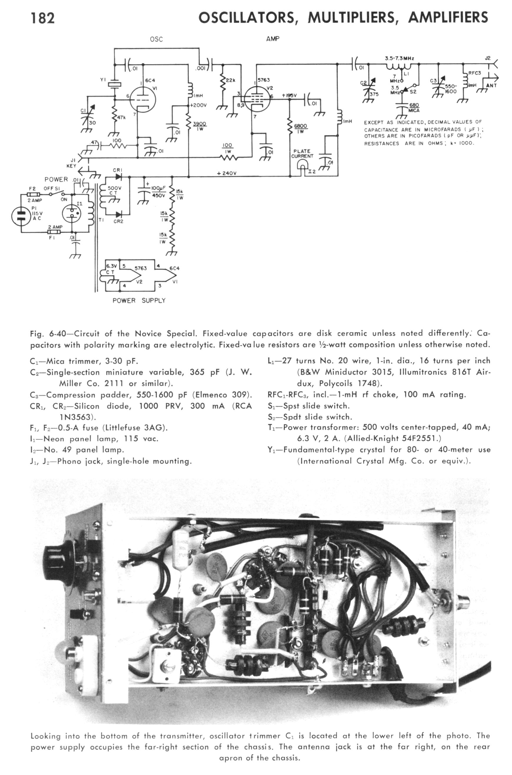
Click here to see the original schematic that i used, as published in the above mentioned 1970 ARRL Handbook.
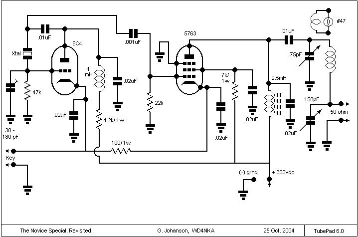
Click here to see my adaptation, which really isn't all that different, but hey, it sure is a fine excuse to show off the "RSGB" 1960's style schematic symbols from the TubePad Library! TubePad 6.0 (Beta) can be downloaded free from this site. Schematic is "drawn" in Paint, and saved in .jpg or .gif format for posting.
In my case, as always, i decided to revisit this rig in the same manner i revisit all the classics: with the contents of my junque box. Which often means some departure from original design, but hopefully, not too far. In my case, i opted to begin with the power supply, having on hand a 360v c.t. transformer, a 6 Hy choke and a couple 450v filter caps to make a full wave rectifier with pi filtering. A 35k 40 watt resistor serves as the bleeder. This was actually quite a bit more power and voltage than required, but i thought i would try it anyway.


Here is an up close view of the rectifier and filter caps. These are mounted on a phenolic strip which is spaced from the metal chassis by two ceramic stand-offs. The two diodes which form the full wave rectifier are mounted on the phenol board, one on each side of the cap. All transformer and output wiring are attached hereto. It is a tight squeeze, figuring in the mA meter.

The transmitter itself is housed in what used to be the cabinet of a piece of test equipment. The original chassis was stripped and re-used. Since the former unit was a hybrid, there was a huge gaping square were the printed circuit board went. This had to be filled with a piece of high-voltage rated Phenolic stock, cut to size. Most of the transmitter circuit is built upon this board. The tube sockets were fit into holes drilled to fit the pins, and then secured by 4-40 screws. Upper left is the 5763. To the right of it is the 6C4, and between them, slightly lower is an octal socket carrying two xtals which are switchable from the front panel. Lower right is the output indicator: a #47 pilot lamp. Next to it is the load control cap, around 150 pF, and next to it, the plate tuning cap, 75pF. Above it is the final tank coil, wound "Sutter" style, approx 2" diameter, and tapped from the load control cap. Just on top of the load cap is the opening for the oscillator grid cap, which "shapes" the xtal.

Just to orient you, the tube pins to the left are from the 5763, and center is the 6C4. The octal is the xtal socket. The red and black jacks are for the key. The thicker bare copper wire is the ground bus. Power is taken from the rear apron jack at the bottom, which is in reality a 7-pin tube base. Yes, that's right, a mini- tube base! These came with a pre-tinned bracket which soldered in place directly to the chassis' rear apron. No screw holes to drill! A miniature version of the old octal power receptacles. to the right of the power input is the SO239 coax jack. In reality, the circuit faithfully follows the original handbook version, except for the pilot lamp: in mine, it measures output. The original registers current dip. Since i have a mA meter on the PS, i figured it might be handier to toss a loop near the hot end of the tank, and make this Glow-Bug glow even brighter.

Here is the completed rig. At center left is the indicator lamp bezel, next to it the load control, and then the tune. Below the lamp is the key jack. Next to this, the xtal switch. The cabinet is spray painted a dark gray hammertone, and the front panel is Hallicrafter light grey. This is pretty much the colour scheme of all my home brew rigs. This way they all match, and look pretty nice all together. At least, that's the idea. The knobs are from an Echophone EC-1. Harvey would be proud.
One thing i did like in the way this turned out: it's a later era rig, so i managed pretty much an early 1960's rounded-edge cabinet look. Now, if will work as nice as it looks, we'll be satisfied.

Here you can see the power input jack and the antenna jack, with corresponding holes punched thru the cabinet to accommodate. I tried to make this rig smack a bit of Johnson-in-miniature. Thus, it is dubbed the "Mini BA", or Canoe Anchor. The bottom has felt feet which i swiped from an old Regency which was dozing off on the cabinet. Sorry, you snooze, you lose! In the process of assembly and repeated openings and closings, some of the paint has chipped, so there will be another session with the spray can.

Here she is, complete and ready to tune up into the dipole with that Kenwood antenna tuner. Actually, it does well enough with it's pi circuit alone. Pretty nice grouping, but all was not well.
In my past, i have gotten away with running 6L6 rigs well into the 50 watt arena on class C. That's all fine and good with the bull-dog 6AG7 pentode oscillators and hefty 807s and large envelope octals, but on these little minis, i discovered something: Bad News!
I was running well over 100v higher than tube rating, achieving a dip at 65-70mA at 400 plus volts, danged near 30 watts input, and lighting a 25 watt bulb full brilliance! And you had to dip very, very quickly or else the plate of the 5763 lit up like a Christmas tree! And the poor 6C4 just could not find stable footing. I managed to stabilise things for the most part, but tuning the final greatly pulled the xtal, there was no decoupling the oscillator from the final without the final losing the grid current and again lighting up the plate cherry red-hot! I could not tame the oscillator, who wanted to see 200v, not 325v dropped thru a mammoth voltage divider!
Finally, i tossed in the towel and resigned to the only solution: Another, lower volt power supply.

This was not gonna be easy, because i didn't have really another decent chassis to build on. And i didn't want to wait till Christmas to finish this project. As i cast about, my eye fell on an old computer power supply culled from an old 386 machine. I knew i had the proper transformer: i wonder if it would fit? So i tore out the innards, mounted a thick phenolic deck in the former computer power supply cabinet, and rested the transformer atop this deck. Yes! It just cleared! This transformer had a high voltage secondary of 130v, so i wired a voltage doubler, finding a couple 20uF/ 450v axial electrolytics in the junque box, and another pair of diodes. Taking this mess to work, i drilled and wired the supply together. The result is not near as pretty as the former supply (which will now be paired with another, future MOPA) but much more palatable to the transmitter! Gone, however, is the nice mA meter. And the handy carrying handle. But, not bad considering it all fit in a nice compact box. You can see i left the fan in. I have to add a switch, fuse and Bleeder yet.
But the radio is much, much tamer, and has a far more stable note, and the drift factor is not near what it was, in fact, there is no drift to speak of after warm up for a few minutes. She handles FT-243 xtals fine, but really likes the HC6-U types especially!

Here you can see the power supply hookup. Since the Kenwood antenna tuner is in use, the loading cap is fully unmeshed, the tuner taking over the output control, essentially. Without the tuner, load and plate tune come to rest at half mesh each, just the way i like it! The output is now a bit less hair-raising, about 10 watts. The plate voltage to the final (5763) is now just under 300 volts, dipping at about 45 mA. I have a 15 watt lamp for a dummy load, and it lights up, only not to full brilliance, but close enough to let me know that RF is definitely there!
Mission Accomplished! Now to get that dipole up in the air where it was before the hurricanes!

Well, here's the parting shot. Far left is the Champion, and next is the (yuck) new power supply that's definitely gonna get a face lift --- next, the Novice Special, cabinet off for final touch-up, next to right, the antenna tuner, and sitting atop it, the 15 watt lamp. It's all temporarily sitting on a board on a stool. You can just see the HT-37 on the upper right trying to get into the picture. I plan to use the Q5'er with this, but for now i am using my HW-101 as the receiver, and switching an antenna switch back and forth for sending and receiving. See ya on 7031 or 7050!

....Ahh, yes, the poor bride left stranded at the altar! Well, she found a new friend, the trusty, dusty, slat-board 6V6er. So all is well in the kingdom, and they all lived happily ever after! Power supply, far left, then the 6V6er and Pi tuning adapter, and to the right of that, the antenna tuner with the Champion on top.

Do you remember me referring to the "Sutter" type coils? Here is an example of one atop the Slat board 6V6er. Solid core copper wire wound thru Bakelite, phenolic or lexan strips to hold shape. This particular coil is 3" in diameter. It was originally wound as a tank with antenna link, the wire antenna base clipped to the hot end of the link, and the counterpoise to the cold end. You can see the link leads poking straight up. But right now i have it set up for pi output tuning. If carefully made in the manner Fred Sutter outlined in his 1938 QST article "The QSL-40", absolutely beautiful coils can be made to rival Air Dux or any other commercial product.


