Since i first posted the Regenerodyne project back in june, there has been lots of feedback from folks who have decided to make one themselves. In fact, i have been, actually, embarrased to not be able to respond to some at the technical level they apparently needed. Unfortunately, an engineer i am not. But like many hams and homebrew enthusiasts, i can hybrid circuits together. Whether or not they will work is quite another story . . .
But i am convinced that most folks can do likewise. If they try.
I got the idea to do this page when folks began sharing their frustrations, and later, successes with me via e-mail. I began to get scanned images of their work. And man, was i ever impressed! Hence, this little Regenerodyne Gallery is not only meant to exhibit the hard work of homebrewers and enthusiasts, but also to tell a story of trial and perseverance. Many builders have to adapt, and re-design the R-dyne to suit their needs, which was the whole point of the Regenerodyne article from the start. To make it work for you! Some had to re-select tubes, dealing with different operating dynamics which called for perhaps a different front end, or detector variations, or re-designed mixers. This makes their products uniquely their own.
Regenerodyne builders can't just go to an old magazine article, textbook or handbook and look up "Regenerodyne" and get help. It won't be there. I made the name up in an effort to distinguish this design from the Jones' "Super-Gainer". While i am sure folks have used this concept in the past as a unitised design, especially in Direct conversion sets of the '70s and '80s, i have not seen any definative treatment on the regenerative detector used in this way. Therefore, these builders are striking out on their own, at least, as far as one is able to these days, dealing with tube circuits.
Much credit is owed to the Glowbugs group as a source of not only information, but encouragement as well. In 1999, when i first joined this group i suggested the name 'Regenerodyne' to see what the consensus was as far as an appropriate name for the project i had described to them. (It's original name was the "Crystal-Regenerative" receiver, to note the fact that a xtal controlled LO was employed.) It was generally conceeded that "Regenerodyne" was indeed an appropriate name, and so it stuck. Although now perhaps unbeknownced to the Glowbug group, the name "Regenerodyne" is a Glowbugs Original. Thanx again, guys and gals!
As for the following exhibits, i will post them as i can, organising the jpg's and the accompanying narratives, as and if i get them. Some of these images are fair sized files, so please be patient with the time it may take some dial-up connections to download them. I try to keep jpgs under 50Kb.
Before i forget it, let me remind you that if you would like to show your Regenerodyne gem to the whole world, you are invited! Contact me at: [email protected]
Now, as Jimmy used to say on the Mickey Mouse Club, "On with the Show!"
Exhibit A.
(Gary's original Regenerodyne)
 Well, i figured the best place to start is right here at home. These
are some new pictures i took of my own two versions, built exactly as
the schematic featured on the Regenerodyne Project page shows.
Well, i figured the best place to start is right here at home. These
are some new pictures i took of my own two versions, built exactly as
the schematic featured on the Regenerodyne Project page shows.
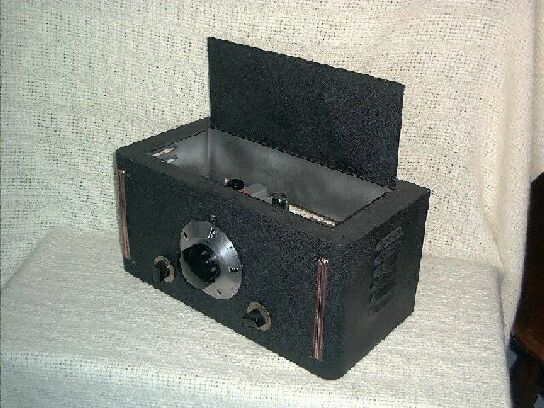
The first picture, shown here to the right (hopefully) is the larger of the two, which sports a PW reduction gear and the ubiquitous HRO dial. The cabinet itself is a rescued metal Bud steel cabinet dating to the late 1930's, of course. The paint is wrinkle-finish black. All coils are mounted beneath the enclosed chassis. The next photo in line shows the front panel minus the cabinet.
 The succession of photos will show how the chassis itself is an enclosed
box. Every effort was made to provide mechanical and thermal stability.
One nice thing about keeping frequency determining inductances within
a sealed chassis is that the heat generated by the tubes have no effect
on them. On this model, i have opted not to use a band select switch,
although one could be easily added: there is tons of room to do it.
The succession of photos will show how the chassis itself is an enclosed
box. Every effort was made to provide mechanical and thermal stability.
One nice thing about keeping frequency determining inductances within
a sealed chassis is that the heat generated by the tubes have no effect
on them. On this model, i have opted not to use a band select switch,
although one could be easily added: there is tons of room to do it.
The combination 100pf variable and PW gear drive makes a bandspread superfluous, hence the only controls on the front panel are the antenna input tuning (only one of the gangs are connected), the main tuning, and the reactance (regeneration) control. Headphone jack is on the rear apron. This set uses a low impedance audio output.
The third photo is a bird's eye view showing tube placement. Note that
a fair distance exists between tubes. The three tubes are, from lower
left and clockwise, the 6J7 mixer, positioned near the front-end LC
directly under chassis. A shielded wire brings the signal from the
so-239 connector due to the distance. the next tube is the 6C5 pierce
LO, and next the 6SN7 JAN dual triode, detector and audio stage. The
plate to voice coil transformer you see is for the low-impedance phones.
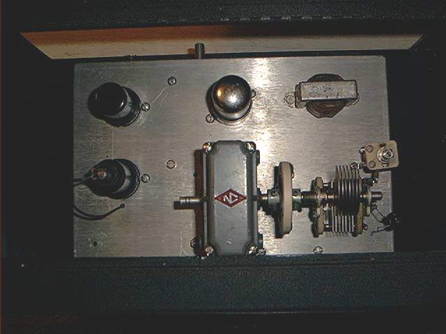
As you might have noticed, there is a trim cap across the 100 pf variable. This is the dial calibration cap. You might notice a silver-mica cap only partly soldered to the cap. This was used to pad me on band until I installed the calibration cap. Calibration need only be accomplished once, for all bands ( 20, 30, and 40m.)
Remembering that the whole concept of the design is simplicity, there are actually very few controlls on this receiver. It behaves similarly to any well built regen, with enhanced selectivity. The primary feature of this design is instant band changing and consistent dial calibration from band to band (provided consistent LO xtals are employed), and a tunable detector which tunes a constant, low frequency range. The particular IF in this receiver is 3.0 - 3.5 mc. It is almost immune to antenna load variations, and the 3 mc IF makes images almost no problem, save for very loud local images. We had some commercial marine stations nearby, and i took care of their images with an added LC at the front end. And that was only on my prototype, not on the receiver we see here.
 Before we tour the underside wiring, i would like to show another
perspective of the chassis construction. First thing you will notice
is that the chassis box itself cost me $ 3.75. That was a LONG time
ago. I bought 2 of these puppies, at the time a pretty good deal. I
never took off the tag. The bottom plate has been removed, as you can
see the screw-holes.
Before we tour the underside wiring, i would like to show another
perspective of the chassis construction. First thing you will notice
is that the chassis box itself cost me $ 3.75. That was a LONG time
ago. I bought 2 of these puppies, at the time a pretty good deal. I
never took off the tag. The bottom plate has been removed, as you can
see the screw-holes.
In this photo you will have a view of the rear apron with LO xtal plugged in. The plate to voice coil transformer is mounted directly above the headphone jack. The terminal strip beside the phone jack contain the power inputs for the B+, Filament and Ground. The chassis is also separately grounded to the external power supply by a copper braid. I have found that not relying on the electrical ground from the power supply, but rather a separate chassis to chassis ground goes a long way in reducing common-mode hum reception, loops, and other annoying phenomenae. And, of course, the use of a separate and outboard power supply is standard operating proceedure here at WD4NKA. At the extreme end of the rear apron is the SO-239 coax female jack (a female named 'Jack'?) The antenna LC is wound to receive a lower impedance antenna, although I can run just about anything from a dipole to a window screen for an antenna. This is an amazingly sensitive box, yet because the detector is isolated from the antenna dynamics, and operating at a low frequency, the common grid-blocking problems normal to straight regens are hardly problematic. The antenna tuning control serves two functions in this regard: RF gain (and by default, therefor, a volume control), an antenna reactance regulator, that is, an antenna can be detuned to avoid certain loading effects. It also serves as part of band selecting, similar to the Drake 1 and 2 series receivers. Because one can tune both images, it is possible to get two bands with each xtal.
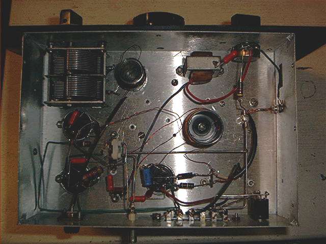 The photo on the right shows the bottom cover off, exposing the
underchassis wiring. Note that there really isn't an awful lot, and
both coils are underchassis mounted. I have found really no difference
between top mounting the coils or doing what i have done here. In this
case i had plenty of room, and the enclosed chassis provides great
shielding. I have tried to make leads as close as possible, but i have
found that a balance has to be maintained with the idea of short point
wiring. When you have to run long lengths of wire from the input or
output ports of your device, there is opportuninty for these long runs
to pick up stray RF, defeating the whole point of short-point connections.
This can be addressed with shielded wire, but i have found that spacing out
the individual stages, while keeping intra-point wiring short, minimizes
those long runs to the antenna jack, the headphone jack, etc. The only
shielded wire i need to run is from the Mixer to the antenna connect. On this
subject, i have found that keeping some discrete components at 90 degrees
in position one from the other goes further in preventing stray coupling.
You might notice the dual-ganged tuning cap for the front end. This is
a precaution due to image experience with my original prototype. Only
one gang is used here in that i found birdies (images) not to be a real
problem, and i did not, therefore, have to wind and mount another coil.
The photo on the right shows the bottom cover off, exposing the
underchassis wiring. Note that there really isn't an awful lot, and
both coils are underchassis mounted. I have found really no difference
between top mounting the coils or doing what i have done here. In this
case i had plenty of room, and the enclosed chassis provides great
shielding. I have tried to make leads as close as possible, but i have
found that a balance has to be maintained with the idea of short point
wiring. When you have to run long lengths of wire from the input or
output ports of your device, there is opportuninty for these long runs
to pick up stray RF, defeating the whole point of short-point connections.
This can be addressed with shielded wire, but i have found that spacing out
the individual stages, while keeping intra-point wiring short, minimizes
those long runs to the antenna jack, the headphone jack, etc. The only
shielded wire i need to run is from the Mixer to the antenna connect. On this
subject, i have found that keeping some discrete components at 90 degrees
in position one from the other goes further in preventing stray coupling.
You might notice the dual-ganged tuning cap for the front end. This is
a precaution due to image experience with my original prototype. Only
one gang is used here in that i found birdies (images) not to be a real
problem, and i did not, therefore, have to wind and mount another coil.
This receiver took three days to build. Two days to actually build, and one day to work the bugs out, which involved a re-design of the mixer. The first design had the LO injecting the 6J7 inductively via the front end LC, which worked fabulously on the prototype, but was absolutely non- functional on the finished piece! So i went with convention (arrrgh!!) and cathode injected the mixer thru a cap, vis. schematic on the R-dyne construction page. Exhibit B is the little R-dyne, the "Eavesdropper" which i built for travel and portability. It took only one day and worked straight 'way. I have had these receivers for some years, now, and they have proven to be very reliable, functional, and durable. Simple to build and operate, this has been a very satisfactory project.